8 min read
How to calculate a PoE switch budget before buying
A practical PoE switch budget calculation for cameras and access points, covering classes, port limits, headroom, and overload behavior.
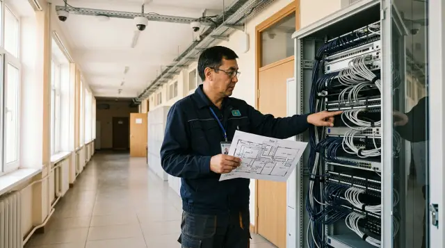
Buying a PoE switch by socket count does not work. A sound calculation must pass four constraints at once: the power standard, the maximum power of each port, the total PoE budget, and the power that the chosen supply configuration retains after a failure. If you check only the sum of watts in a spreadsheet, the design can look correct while still leaving an outdoor camera without heat or an access point without some of its radios.
Calculate the budget before choosing a switch SKU, but after defining device operating modes. You need the maximum requirements of the cameras, access points, phones, panels, and converters with their intended functions, not average readings from a lab. Convert that demand to the PSE side, assign it to ports, add explicit headroom, and set a shutdown order. That calculation can survive a procurement review and be verified during commissioning.
Separate four different constraints first
The headline figure "370 W PoE budget" answers only how much power the switch can distribute across its ports. It does not say whether one port can deliver the required 60 W, whether every connector supports the higher class, or whether 370 W remains available with the installed power supply. Check these limits separately.
PoE documentation names two parties. The PSE, or Power Sourcing Equipment, supplies power and is usually a switch or injector. The PD, or Powered Device, receives it and may be a camera, access point, phone, or panel. The cable between them turns some energy into heat. That is why "30 W at the port" and "25.5 W available to the device" describe one class from opposite sides of the cable.
Write down four lines for every switch candidate:
- the PoE budget available with the power supply you will actually order;
- the maximum power and supported PoE type on every required port;
- the number of ports that can support the required class at the same time;
- the budget retained under the intended power supply redundancy policy.
The last line often changes the decision. In a modular switch, the chassis, fans, and line cards take some power supply capacity first, and PoE receives what remains. On models with two supplies, a combined mode may add their capacity or keep one unit in reserve. A shared series name does not guarantee an identical budget. The supply SKU, number of supplies, and redundancy policy all matter.
The rack also has an input power limit. A published PoE budget is measured at the PSE output, while the UPS and circuit breaker see the input power of the whole switch, including conversion losses, its own electronics, and fans. Do not subtract those losses from the PoE budget a second time. Calculate the UPS separately from maximum input power and the required runtime.
A device class is not its normal consumption
A PoE class sets the upper boundary of negotiated power, not the device's constant draw. You need that upper boundary to guarantee startup. Current consumption becomes useful later for monitoring and more efficient allocation, but it is a dangerous basis for procurement.
In its IEEE 802.3bt overview, the Ethernet Alliance lists the PSE limits and the guaranteed power at the PD. Keep both columns in view. Type 1 under IEEE 802.3af has these "PSE / PD" pairs: class 1 is 4 / 3.84 W, class 2 is 7 / 6.49 W, and class 3 is 15.4 / 13 W. The remaining types have higher limits:
- Type 2, IEEE 802.3at, class 4: 30 W at the PSE and 25.5 W at the PD;
- Type 3, IEEE 802.3bt, class 5: 45 W at the PSE and 40 W at the PD;
- Type 3, IEEE 802.3bt, class 6: 60 W at the PSE and 51 W at the PD;
- Type 4, IEEE 802.3bt, class 7: 75 W at the PSE and 62 W at the PD;
- Type 4, IEEE 802.3bt, class 8: 90 W at the PSE and 71.3 W at the PD.
Those numbers expose a common mistake. If a camera data sheet says "25 W maximum at the input," you cannot enter 25 W in the PSE load column and treat the cable as lossless. To guarantee operation across a 100 m channel, the camera may require Type 2, while the switch needs up to 30 W on that port. If the manufacturer explicitly gives maximum power requested from the PSE, use it, but read the parameter name and notes first.
Class 0, or an unknown class, needs separate attention. An old device or one that negotiates poorly may not report an exact requirement, so the switch reserves the upper boundary of the base class. Cisco describes this logic in its Catalyst 3850 guide: after detecting a PD, the switch makes an initial allocation by class, then may refine it through LLDP or a proprietary protocol. You save budget only when both ends negotiate correctly and the selected accounting mode uses the result.
IEEE 802.3bt added Autoclass. The PSE measures consumption while the PD deliberately presents its known maximum and can then allocate a more precise value that accounts for the channel. It is a useful mechanism, but a PoE++ label alone does not prove that a port supports it. Check Autoclass support in the documentation for both devices.
Read a device data sheet as a list of modes
Every camera and access point needs the maximum profile for your exact configuration. A "typical 8 W" line describes an ordinary moment, not a cold night, PTZ movement, an active IR illuminator, or every radio running. Keep the typical value in the project schedule if you want to estimate normal operation, but put the calculated maximum beside it.
For a camera, check the enclosure and front glass heaters, IR illumination, PTZ motors, wiper, visible light, microphone, speaker, and power delivered to external equipment through the camera. Not every function necessarily peaks at once, but only manufacturer documentation gives you grounds to exclude a combination. In its paper on typical and maximum power, Axis defines the maximum as the worst operating condition for temperature and voltage, including a momentary peak. It also gives an example camera that uses 4.7 W in a typical mode with the heater and IR off, but 12.6 W at maximum. Add only the typical figures for twenty such cameras and 158 W of possible PD-side load disappears from the calculation.
For an access point, check the number of active bands, radio chain configuration, channel width, second Ethernet port, USB, and PoE-out. Insufficient power does not always turn the access point off completely. It may enter a reduced mode. Cisco documentation for some access points, for example, describes disabling USB and an auxiliary Ethernet port or reducing the radio configuration when a lower class supplies power. A green light and a visible SSID do not prove that the access point matches the design.
Build a schedule with the exact SKU, hardware version, and quantity. For each row, record the needed functions, minimum port standard, maximum PD input, and calculated PSE power. Give startup conditions and priority their own fields. "Cold start, illuminator on, motor moving" says more than a general note that the camera is on.
Do not replace a SKU with the word "camera." Two similar-looking models can draw different power, and the next hardware revision of an access point may move from Type 2 to Type 3. If the final SKU is not known, set a procurement boundary such as "no more than 25.5 W at the PD input, full function on IEEE 802.3at." The supplier must then stay within the calculation or recalculate the switch.
Keep the working calculation on the switch side
Add PSE power across the devices because that is the budget published by the switch manufacturer. The formula is simple once every input is expressed on the same side:
P_установленная = Σ(N_i × PSE_i)
P_проектная = P_установленная + P_резерв_портов + P_резерв_неопределенности
Consider a floor with 18 indoor class 3 cameras, 6 outdoor class 4 cameras, and 8 class 4 access points. Suppose a review of the data sheets and negotiation behavior shows that the switch reserves 15.4 W, 30 W, and 30 W on the corresponding ports. The PSE-side maximum is:
18 × 15,4 = 277,2 Вт
 6 × 30   = 180,0 Вт
 8 × 30   = 240,0 Вт
Итого     = 697,2 Вт
A switch with a 740 W total budget technically passes, but leaves only 42.8 W. That is 6.1% of the installed load, not enough for even two additional class 3 cameras and one class 4 access point at once. The marketing phrase "PoE on all 48 ports" does not help either. Forty-eight ports at 30 W would require 1,440 W if every device requested its maximum.
Now define the expansion explicitly: four future class 3 cameras and two class 4 access points. Port reserve is 4 × 15.4 + 2 × 30 = 121.6 W. Add 20% of the known installed load for design uncertainty: 697.2 × 0.20 = 139.44 W. The result is 958.24 W. Select a configuration with at least that much available budget under the required power supply mode.
Twenty percent is not an IEEE rule. It is an engineering choice for a project in which cable lengths, firmware, and device modes may still change. A fully fixed specification may justify less headroom. A site with unapproved outdoor cameras and planned expansion will need more. Showing the reserve as separate lines matters more than debating a magic percentage.
Do not apply the percentage to future ports twice. In the example, the capacity for six specific future devices already appears as 121.6 W. The 20% margin covers uncertainty in the known installation. If the customer says only "we may add about ten devices later," assign a class and count to that expansion. Otherwise, nobody can verify the reserve.
The total passes only after every port passes
After calculating total power, build a port matrix. Every device must land on a connector that supports its type, class, number of powered pairs, and required power. Read specifications especially carefully when IEEE 802.3bt is available on only some ports or when the higher class depends on the installed power supply.
Check at least these points for every group:
- The port supports the PD standard and class.
- Its PSE-side maximum meets the requirement.
- Enough such ports can operate at the same time.
- The Ethernet speed matches the access point and cabling system.
- The switch temperature and channel length limits are met.
Speed and power are linked by product design, not arithmetic. An access point may need Multigigabit Ethernet and Type 3 while the selected switch offers high power on gigabit ports and the needed speed on PoE+ ports. The total watts will be correct, yet no connector will fit. A device-to-port matrix catches that problem before procurement.
Check the cable too. PoE standards account for losses in a compatible channel up to 100 m, so the difference between PSE and PD figures is deliberate. The standard calculation cannot fix a conductor with excessive resistance, a poor contact, an unsuitable patch cord, or too much heat in a dense bundle. With higher-power four-pair delivery, the quality of all four pairs affects both available power and cable temperature.
Do not treat an unnamed injector as insurance. It adds a power supply, an outlet, a failure point, and another UPS redundancy question. An injector makes sense for one remote device or a specific class mismatch. If the design has dozens of them, it is usually hiding the wrong switch selection.
Headroom should buy a defined expansion
"Leave 30% for the future" is a weak requirement until someone names the ports and classes of those future devices. Spare power without suitable free ports is useless, and free ports without watts are equally useless. The reserve should answer a specific scenario: four more Type 1 cameras, two Type 2 access points, or one Type 3 PTZ camera.
I divide reserve into three parts. The first covers approved devices at their maximum modes. The second is assigned to known expansion with defined port counts and classes. The third covers uncertainty, such as replacing an access point with a more demanding model or changing a cable route. Do not merge these lines in the final schedule. After the first equipment change, nobody would know which reserve had already been spent.
For a long service life, reserve the class distribution as well as the power. Six spare PoE+ ports cannot replace two future Type 3 ports. If a Wi-Fi upgrade is expected, check the likely power and speed requirements of that access point generation even if the units will be bought two years later.
Some designers recommend calculating every port at the full 90 W. The advice is popular because it looks safe and avoids reading data sheets. For a normal mix of cameras and access points, it leads to expensive power supplies, excess heat, and an oversized UPS. Apply the class ceiling to a specific device, not indiscriminately to every connector.
The opposite extreme is worse: take observed consumption and add 10%. At night, camera IR illuminators switch on. Heaters start in freezing weather, and almost every device begins booting together after power returns. An average over a working day describes none of those modes.
Overload should drop devices chosen in advance
When the budget runs short, a switch does not have to reduce voltage evenly across every port. It will usually deny a new power request or remove power from a lower-priority port if a higher-priority device asks for unavailable capacity. The exact logic depends on the model, accounting mode, and configuration.
The Junos documentation for PoE priority states the behavior plainly: lower-priority ports shut down first when power is insufficient, and connecting a new device on a high-priority port can remove power from a low-priority port. Port number may determine order among ports at the same level. Giving every port the same "low" value is not neutral. It creates a hidden dependency on physical port placement.
Assign priority by the consequence of an outage. An entrance camera, an access point for operational communications, and a conference phone may belong to different categories even on one floor. Do not mark everything critical. If every port has the highest priority, port order or the switch's internal logic makes the decision again.
A useful policy looks like this:
- critical priority goes to security and communications devices whose immediate loss disrupts site operation;
- high priority goes to main access points and cameras in important areas;
- normal priority goes to secondary cameras, information panels, and future connections;
- port numbers within one level follow a deliberate order;
- power denial events go to the monitoring system.
The accounting mode changes the result too. With class-based reservation, the switch retains the upper limit even when the current draw is small, so the promised power remains assigned to the port. Actual-use accounting packs capacity more tightly, but simultaneous load growth may force the switch to drop ports. Aruba switch guides describe allocation by actual use, class, a configured value, and LLDP. This choice belongs in the calculation, not in a setting left for an installer to decide.
Set warning thresholds separately. An alert at 80% of budget gives an operator time to examine a new port or changed operating mode before a shutdown. Choose the exact percentage around the operations process. An alert is useless if nobody receives it, while a 99% threshold leaves almost no room to react.
A power supply failure changes the calculation
Calculate power redundancy in the state after a failure, not before it. If two supplies together provide enough PoE budget but losing one drops available power below the design figure, that is load sharing rather than full redundancy. The switch may continue forwarding data while some PDs lose power according to their priorities.
Ask the supplier for the budget under every supported configuration. For one supply, you need the available PoE budget and port limits. For two supplies in combined operation, you need the total budget and chassis ceiling. For redundant operation, you need the guaranteed budget after one supply fails. Finally, the supplier should identify which ports turn off, and how quickly, after a supply or input phase fails.
The example critical site requires 958.24 W. If a configuration provides 1,100 W normally but only 740 W after a failure, the 218.24 W difference must map to ports that may be dropped. If no such ports exist, add power, split the load across two switches, or revise the device classes. A chassis does not become redundant merely because it contains two supplies.
Splitting loads across two switches helps when it follows physical risks. Do not put cameras from adjacent critical zones on one unit, and alternate access points between switches so that one failure does not create a continuous coverage hole. Calculate each switch separately. You cannot add both budgets and compare the sum with all loads when a device cable cannot move automatically to the neighboring PSE.
Check the UPS under the worst allowed PoE mode. After utility power fails, the battery must supply the switch electronics, active PDs, and conversion losses. If the battery policy turns off some ports, document that scenario along with their priorities and required runtime.
Commissioning must reproduce the worst mode
The calculation is complete only after testing the installed equipment. For every port, the switch interface should show class, allocated power, actual consumption, priority, and state. A snapshot from one quiet working hour is not enough.
Run two tests. First create the functional maximum: enable IR illumination and heaters through supported controls, move PTZ mechanisms, load the access point radios, and activate intended peripherals. Then perform a controlled PoE restart in groups to observe startup requests and confirm that every device returns in full operating mode.
Save command output or an interface export in this shape:
Port  Priority  Class  Allocated  Actual  State
1/0/1 critical  4      30.0 W     18.7 W  delivering
1/0/2 high      3      15.4 W     11.9 W  delivering
1/0/3 low       4      30.0 W     16.2 W  delivering
Total allocated: 697.2 W
Available:       402.8 W
Column names differ by manufacturer, but you need both allocated and actual values. The first shows how much budget the ports have been promised. The second helps find anomalies and test your assumptions. If an access point receives power, also verify its operating profile in the controller or local interface. A reduced mode may not appear as an obvious message in the PoE table.
Test the overload policy safely. During a maintenance window, temporarily reduce the available budget through a supported setting or attach an approved load without exceeding electrical limits. Confirm that only permitted ports turn off, that the event reaches the log and monitoring system, and that returning power restores devices without manual work. Do not create a short circuit or pull a power supply during production hours just to test the logic.
Record firmware versions and retain the PoE configuration with the test report. Updating the switch or a PD can change LLDP negotiation, an access point's available profile, or telemetry readings. You do not need to repeat the entire building acceptance test after every significant update, but retest the highest classes, camera cold starts, and one controlled low-priority shutdown. This short regression test catches a behavior change before freezing weather or a mass power restoration does.
Put a normal actual-consumption range into monitoring too, but do not confuse it with the safety limit. A camera that normally draws 7 W but suddenly holds 12 W with illumination off deserves a check of its cable, heater, and settings. The reverse can also signal trouble: abnormally low consumption may mean that an access point booted into a reduced profile. Telemetry helps operations only when engineers have a reference mode and an acceptable explanation for deviations.
Attach three artifacts to the procurement specification: the device and mode schedule, the device-to-port matrix, and the calculation for one power supply failure. As a system integrator, GSE.kz can connect equipment selection with infrastructure design and ongoing support, but the source classes and scenarios still need to be fixed in the project. Procurement can then compare verifiable configurations instead of large figures copied from unrelated catalog pages.
If actual allocation differs from the calculation, do not adjust the spreadsheet to match green lights. Find the cause: a different device version, the wrong class, disabled LLDP, another accounting mode, a cabling fault, or a restriction on one port group. You buy a switch once, but cold nights, Wi-Fi upgrades, and power failures recur. In those moments, an honest budget keeps the network working instead of remaining a line in a specification.
Frequently asked questions
How much PoE headroom should a project include?
For a known equipment list, I allow 20-25% above the calculated maximum. If the number of cameras or access points is still changing, calculate expansion capacity separately by free port instead of hiding it inside one percentage.
Can I add up the typical power use of the devices?
You can use that total to estimate normal load and heat output, but not to choose a guaranteed budget. The switch must handle heaters, IR illuminators, radios, and other intended functions turning on at the same time.
Why does a 12 W camera reserve 15.4 W of the budget?
The switch may reserve power from the advertised class rather than the current reading. Class 3 has a 15.4 W upper limit at the PSE even when the camera uses less most of the time.
Is PoE+ enough for a modern access point?
Only if its data sheet promises the required operating mode on 802.3at. Some access points disable USB, some radios, or spatial streams when the available class is too low.
How is the total PoE budget different from port power?
Port power limits one device, while the total budget limits the sum across all active ports. A 370 W switch with PoE+ ports still cannot deliver 60 W through one port.
Do cable losses need a separate allowance?
Yes, if the device data sheet gives power at the PD input while your calculation is at the switch. The simplest approach is to use the maximum PSE power for the negotiated class, which already includes the standard loss allowance.
What happens when a switch exceeds its PoE budget?
The result depends on the model and settings: a new port may stay off, or the switch may remove power from a lower-priority port. Configure the shutdown order and verify it with a load test.
Does a redundant power supply affect the PoE budget?
Yes, but the design depends on the platform. Two supplies may increase available power in load-sharing mode, while a redundant design must retain its budget after one supply fails and therefore has a lower usable limit.
Can I trust the current power reading in the interface?
It is useful telemetry, but it captures a moment rather than the worst operating mode. Record the maximum during a cold start, IR activation, and Wi-Fi load, then compare it with reserved power.
How should I verify a PoE calculation after installation?
Connect every device, enable its highest-power functions, and restart groups of ports. Check allocated and actual power, denial messages, access point operating modes, and the order in which ports lose power.