Power requirements for a server rack: what to request
Power requirements for a server rack: which parameters to request from the building, how to check phases, breakers and grounding, and what to do before commissioning.
Why agree power terms for a server rack in advance
A server rack may fail to start even if a standard outlet is available, because the outlet alone says nothing about spare capacity, number of phases, quality of protective earth (PE) or line protection. For IT equipment this isn’t just formalities: devices expect defined network parameters, and if the building provides different ones, problems appear right after the first power-up.
Practically, power terms for a server rack are a set of specific answers from the building: what power is actually available, where the connection point is, which protections are installed, how grounding is arranged and what is already occupied by other consumers. Without these details it’s easy to buy UPSs, PDUs or servers with no margin and later find that the supply is overloaded or the required line simply doesn't exist in the server room.
Small electrical surprises are especially dangerous. Phase and neutral swapped, a shared neutral across multiple circuits, a poor PE contact or grounding through some random metal path can cause strange symptoms: a server won’t start on the first try, power supplies overheat, UPSs report errors, or protection trips for no apparent reason.
If you don’t agree power in advance, typical risks emerge: downtime and project launch delays due to board or cable rerouting; failure of power supplies and ports because of incorrect connections and poor PE; nuisance tripping of breakers at inrush currents and peak loads; interference and noise causing network and peripheral instability; and disputes with building operation over responsibility and payment for fixes.
A practical example: one rack is installed in an office and everyone plugs into a wall outlet. When multiple servers start and the UPS begins charging batteries, the breaker trips. It turns out the line is already partially loaded by an air conditioner, and the breaker rating and cable cross-section aren’t sized for the new load. If you requested power terms beforehand, this would be visible before buying and installing equipment.
For integrators and manufacturers like GSE.kz, agreed power parameters are also important for correctly selecting servers, UPSs and the distribution scheme in the rack so everything works stably from day one.
What to prepare on your side before requesting information from the building
Before contacting building operations, gather your baseline data. That way you will request exactly what you need and avoid reworking power after equipment purchase.
First, record how many racks are planned now and in the next year. It’s important not only to say “1 rack” but also what will be inside: servers, storage, switches, KVM. Note separately whether the rack will have a UPS and what type of PDUs are needed (basic or metered).
Next, estimate consumption. Usually two numbers are useful: nominal power (for normal operation) and peak power (on startup, updates, full load). Use datasheets and add margin, otherwise breakers may trip at the worst moment. If unsure, make a simple table: model, power supplies, max power, quantity.
Plan the power scheme. One input is simpler, but two independent inputs increase reliability (A/B power, two PDUs, two separate breakers). Decide in advance whether you need single-phase or three-phase power. For a small office rack a single-phase feed is often enough, but as power or density grows three-phase is more convenient for current and load distribution.
If a UPS is planned, determine runtime requirements. It’s not enough to say “long runtime”; specify how many minutes are needed to shut down cleanly or wait for backup. For example, an institution might need 10–15 minutes, while highly critical services may need 20–30 minutes or more.
Briefly define what counts as downtime for you. This helps the building understand priorities: where maximum reliability is required and where brief interruptions during maintenance are acceptable.
What data to request from the building about the feed and phases
The first step in power terms for a server rack is to understand what the building can actually provide in your room, not just overall on site. This saves time: if the maximum allowed power is already used, no rack-mounted breakers will help.
Ask the building engineer or service provider for a short written answer covering several items. It’s convenient to request this by email so there’s no dispute later about who said what.
Minimum dataset to request
- Allocated power: how many kW can be assigned to the room or floor, and whether there is a contract limit.
- Network parameters: 230 V 50 Hz (single-phase) or 400/230 V 50 Hz (three-phase).
- Which conductors are available at the connection point: L1/L2/L3, N (neutral) and PE (protective earth).
- Where the nearest connection point is and who provides access: main distribution board (MDB), floor panel, separate IT board, or board inside the server room.
- Is there redundancy: a second input, a building generator, building UPS, and how fast switching occurs.
After their reply, clarify an important detail about phases: how load is currently distributed across L1/L2/L3. Sometimes three-phase exists on paper but one phase is already loaded with lifts or HVAC, and you can’t add the rack there.
Small example: you plan a rack of 3–4 kW. If the building only offers single-phase 230 V with a 2 kW limit per office, you must either reduce the plan (fewer servers, different UPS) or request a dedicated line from the board with increased allocated power.
If the building has a generator or second input, ask whether your board is actually backed up or only critical circuits (lighting, fire systems) are reserved. This directly affects your rack power scheme and availability expectations.
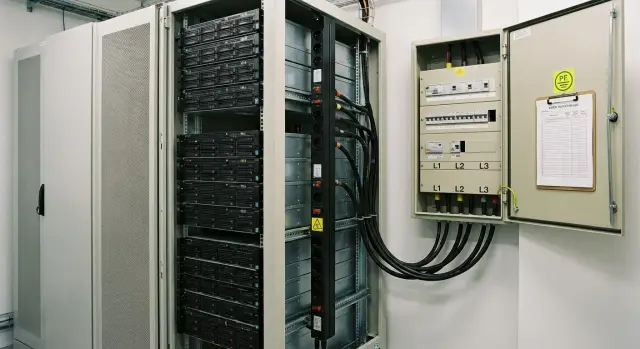
Breakers, protections and the electrical board: what to clarify beforehand
The distribution board and protections often determine more than the outlet next to the rack. If a breaker is chosen as a generic one, servers may trip protection during startup, or a fault can cut power to half the floor. Before installing a rack, agree which circuits will be allocated and how they will be protected.
What to ask the building electrician
Request specifics for your connection in the board: which devices are installed, their ratings, and what is still available.
- How many spare circuits (breakers) can realistically be allocated to the rack and where they are located in the board.
- Type of device: circuit breaker, load break switch, RCBO, is there RCD protection on the line.
- Rated current in amps, whether the line is single- or three-phase, and the cable cross-section to the connection point.
- Breaker characteristic (B, C or D) and whether a device with higher inrush tolerance is acceptable.
- Who is authorized to switch, seal, or change breakers and how access is documented (request procedure, permits, logbook).
Why characteristics and selectivity matter
Servers, UPSs and power supplies have short inrush currents. If an automatic breaker with characteristic B is used by default, it may trip when the whole rack starts or when UPSes switch. C or D characteristics sometimes solve the issue, but this must be coordinated with cable sizing and short-circuit current calculations.
RCDs and RCBOs are another topic. For IT loads they aren’t always desirable: input filters and UPSs can create small leakage currents causing nuisance trips. Sometimes RCDs are required by building rules. In that case confirm type and sensitivity and consider splitting loads across lines.
Selectivity means that on a fault your circuit should trip, not the upstream building feed. Request a diagram showing upstream devices and their ratings.
Example: in an office, two 230 V circuits are planned for one rack. If both are under one common RCD covering multiple offices, a false trip will cut not only the servers but also workstations. It’s better to allocate a separate group for the rack and label it in the board.
Cable runs and connection points inside the rack
Even if power and protections are correct, problems often appear on the last meters: the cable isn’t sized for the current, the route is too long, or the terminating outlet is incorrect. Power terms should include details of the run up to the rack.
Record line parameters: conductor material (copper or aluminium), cross-section, length and expected load. Length matters for voltage drop: the further the board, the higher the required cross-section. If the run crosses several rooms, clarify where joints and junction boxes are — typical hotspots for heating and faults.
Agree on the routing method: trays, conduit, raised floor or dedicated pipe — different fire-safety and access requirements apply. In a server room expect a tidy route without unnecessary loops and space reserved for a second line (for redundancy).
Also clarify how you will terminate in the rack. Confirm the final outlet type (Schuko, IEC C13/C19, terminal block or direct PDU feed), outlet entry position (top or bottom of rack, left or right), tail length inside the rack for sliding servers, whether A/B power is required, and labeling rules (circuit number, board, breaker, phase L1/L2/L3 and where the tag should be).
Simple example: for a rack with two PDUs (A and B) it’s logical to request two separate circuits from different breakers clearly labelled “Rack-01 A” and “Rack-01 B”. Then when installing servers and storage (typical 1U/2U devices) no one confuses inputs, and power checks take minutes, not a day.
Grounding and PE: what to ask and how to verify it’s correct
Grounding in a server room is not a formality. It protects people and equipment from leakage, interference and board faults. Power terms should include a dedicated section about PE and equipotential bonding.
What to request from the building
Start with the building earthing type (for example TN-S or TN-C-S) and ask where PEN is split into N and PE if applicable. It’s important to know in which board this point is located and who is responsible for its condition.
Clarify whether a separate PE busbar exists in the incoming or floor panel and whether it’s connected to the equipotential bonding network (metal structures, cable trays, engineering utilities). For a server room this is critical: all metal parts should be at the same potential.
Request required earthing resistance values and recent measurement reports. Good practice is to have a fresh protocol (after works, reconstruction or at least within scheduled checks) issued by an electrical laboratory.
How to verify on site
Before powering up the rack, check that PE actually reaches the connection point (outlet or PDU input) and that there are no open circuits. Also ensure there are no questionable N–PE jumpers in improper places (for example inside an outlet, inside a PDU, or in a floor panel after the separation point).
A practical minimum: continuity of PE from the board to the outlet or PDU input; no N–PE connections where they shouldn’t be; correct labeling of conductors and busbars (PE, N, phases); rack equipotential bonding where planned; and conformity of measurement protocols (earth resistance, phase-to-neutral loop, RCD/RCBO tests if present).
If grounding seems doubtful (old building, unknown modifications, fluctuating measurements), don’t take risks: order an electrical lab audit and consider running a separate PE conductor from a verified PE busbar. In practice this is often simpler than troubleshooting nuisance trips, interference or damaged power supplies later.
Power quality and redundancy: UPS, bypass and generators
Even with agreed power terms, network quality often decides whether the rack will operate stably. Typical building issues are voltage dips during motor starts (lifts, pumps), short outages, phase imbalance and voltage spikes.
A UPS is necessary if downtime is unacceptable or the mains is unstable. For servers an online double-conversion UPS is commonly used because it better regulates voltage and frequency. Line-interactive units suit only very small loads and stable mains. Choose phase topology according to feed and power: a single rack can be fed from one phase, but at high power or when the rack uses three-phase input consider a three-phase UPS (3/1 or 3/3).
Plan a bypass for UPS maintenance. Manual bypass is simpler and cheaper but requires clear procedures. An automatic bypass helps on UPS failure but still requires that the bypass line can handle the same load.
Before choosing a UPS, ask the building for data or perform measurements: daytime voltage dips and surges, phase imbalance (for three-phase), harmonic levels (especially with many switching power supplies), and frequency/duration of short outages.
If a generator is planned, check start time and frequency stability after start. For example, if the generator stabilizes in 20–40 seconds, the UPS must hold the load with margin and cope with generator waveform quality, otherwise the UPS may switch to batteries unnecessarily.
Rack-mounted UPSes save space but run hotter and complicate access. Floor UPSes are easier to service, simpler to ventilate and allow safer access.
Checks before powering equipment: step-by-step order
Even with agreed power terms, perform a short on-site check before the first power-up. This catches swapped circuits, phase sequence errors and grounding issues that later look like random reboots and failed power supplies.
Order of checks
-
Visual inspection. Check the board, breakers and labeling. Look for cable damage, cracked outlets, signs of heating (discolored plastic, melting), and loose terminals. Confirm the line is the one intended for the rack.
-
Measure voltage and frequency. With a multimeter or power analyzer check voltages at outlets/PDU and that the setup matches the scheme: single- or three-phase, and presence of neutral where needed. Frequency should be stable around 50 Hz.
-
For three-phase systems check phase sequence and imbalance. Incorrect phase sequence is critical for some equipment and UPSes. Compare phase-to-phase and phase-to-neutral voltages to ensure no significant imbalance, especially if the rack uses many single-phase power supplies.
-
Check PE (protective earth). Ensure PE is present and connected: continuity test, earth loop measurements if instruments are available, and confirm no dangerous potential on rack frames and equipment. Any doubts are a reason to stop and call an electrician.
-
Load test. First connect a safe test load or power up equipment one by one, watching for cable heating, smells, or noises in the board and outlets.
After these checks power up in sequence: UPS first, then PDU, then network/storage equipment, and finally servers. For example, in an office rack of 6–8 kW a weak terminal often appears: with no load everything is fine, but during stepwise startup heating and smells appear at a loose terminal. Record measurements and dates for later comparison.
Example: preparing power for a single rack in an office or institution
Initial data: one 42U rack containing 2 servers, storage, 2 switches and a rack UPS. The goal is to get clear power terms and commission equipment without surprises.
Estimate load from datasheets. Suppose servers are 800 W each, storage 700 W, switches 150 W each. Total about 2.6 kW. Add margin for peaks and growth (typically 30–50%) resulting in 3.5–4 kW. Choose breaker, cable and UPS capacity off this with practical loading of no more than 70–80% of the circuit rating.
Implement A/B power: two independent inputs to the rack, two PDUs (or a PDU with dual inputs if supported), and servers with dual PSUs each on separate inputs. If the building only provides one input, A/B can be simulated with a UPS and bypass but explicitly note the lack of external independence.
If three-phase is available, distribute loads to balance phases (e.g., some PDU outlets on L1, others on L2 and L3). If single-phase, ensure current margin and that terminals and breaker don’t overheat.
Request documents from the building:
- single-line diagram showing from where the rack line is taken
- document dividing ownership and responsibility
- measurement reports (earth resistance, phase-to-neutral loop, RCD/RCBO tests if present)
- line parameters: phases/voltage, allocated power, breaker type and rating, cable brand and cross-section
Before powering, perform basic checks and record results:
- presence of PE and correct connection (PE is not swapped with N)
- voltage and phase sequence (if 3-phase)
- terminal torque and absence of heating or burning marks in the breaker and board
- test RCD/RCBO operation within allowed procedure
- trial startup: UPS without load, then PDUs and equipment sequentially
Typical issues found at this stage: missing separate PE, N and PE swapped, actual line weaker than declared (thin cable, lower breaker rating), phase imbalance from uneven outlet layout.
Common mistakes and how to avoid them
The costliest mistake starts with the simple phrase: “Our rack is 5 kW, so a 5 kW line is enough.” In reality not only watts matter, but currents on each phase, reserve for breakers, earth quality and how you will maintain power without downtime.
Below are problems that often surface after installation and how to prevent them in the power terms phase.
Errors in calculations and load distribution
People often sum only steady-state power and forget inrush currents (especially for UPSs and PSUs), future growth and losses. Add margin for the line and breakers and plan for the next 12–24 months.
If three-phase is available but the rack is connected to a single phase, imbalance and contact heating occur. Pre-allocate PDUs and inputs across phases and check currents with clamp meters after power-up.
Errors in connections and protection
Often household extension cords and power strips are used instead of proper PDUs. They overheat, have poor contacts and aren’t rated for continuous loads. Use server-grade PDUs with the required outlet types and clear A/B labeling.
A dangerous mix-up is swapping N and PE or using the rack frame as a grounding conductor. Earth must be a separate PE conductor back to the board with measured resistance and continuity; the rack chassis is only bonded to PE, not a substitute for it.
RCDs are frequently installed “just in case” and then cause nuisance trips due to UPS leakage and filters. Before choosing protection confirm RCD type, trip settings and where it’s actually required.
Plan for maintenance: a clear bypass (if UPS exists), access to the board, labeling of circuits and outlets. When GSE.kz delivers and commissions racks, these small details usually determine whether startup is calm or problematic.
Short checklist and next steps
To avoid discovering critical details on installation day, gather the building’s answers in writing in advance. If something is “approximate” or “as usual,” stop and clarify.
What to request from the building (before procurement and installation)
- Feed and phases: single- or three-phase supply, board diagram, actual voltage and frequency.
- Power limit: allocated power for your zone, allowable peaks, any time or group restrictions.
- Protections: breaker ratings, RCD/RCBO types and settings, selectivity, and who has access to the board.
- Run to the rack: cable type and cross-section, route length, routing method, existence of a separate line for UPS and bypass.
- Grounding: presence of PE, connection point, earthing system parameters, and whether equipotential bonding with lightning protection is allowed per project.
Before powering equipment (on the work day)
- Measure and record: input voltage, phase imbalance (if three-phase), PE continuity, polarity and absence of phase on rack chassis.
- Label: breakers, cables, PDUs, A and B lines and rack outlets.
- Perform a load test: simulated load or stepwise power-up (UPS, then PDUs and equipment); monitor phase currents.
- Check protections: correct behavior in fault scenarios (disconnection of line A or B) and bypass operation without surprises.
- Start in steps: network and storage first, compute next, and non-critical devices last.
For acceptance it’s helpful to have: a single-line diagram, a measurement report (voltage, PE), a protection test protocol and labeling, an A/B power scheme and a maintenance plan. If non-stop maintenance is required, agree in advance what works are allowed live, how to switch to bypass, who is responsible and what windows are available.
Next step, if in doubt or the rack is power-hungry: invite a systems integrator for an inspection. In practice this helps immediately select a rack, UPS and servers that match the available infrastructure (for example rack-server configurations GSE S200) and avoid redoing boards and routes. If you operate in Kazakhstan, such tasks are commonly handled by GSE.kz (gse.kz) as a manufacturer and integrator: from equipment selection to commissioning with regard to real power parameters on site.