Liquid cooling for GPUs: when it pays off in HPC
Liquid cooling for GPUs increases HPC density but requires calculations for heat, water, service and risks. Selection criteria and room checks.
Where the question of liquid cooling for GPU clusters starts
The question of liquid cooling for GPUs usually appears not out of curiosity but out of pain: new generations of accelerators give off more heat, and the usual setup with cold aisles and powerful CRAC/chillers starts to reach its limits. First, inlet temperatures rise, then fans spin up, noise becomes noticeable even outside the door, and stability under load drops.
Air stops coping when rack power density grows faster than you can safely provide cold airflow and remove hot air. Hot spots and recirculation appear, and every extra kilowatt becomes disproportionately expensive: more fans, higher power consumption, less fault margin.
It’s important to be clear about what you want to improve. Sometimes the goal is to fit more GPUs into the existing room without expanding. Sometimes it’s to reduce throttling and unexpected reboots during long jobs. Sometimes the main constraint isn’t the rack but the building’s power and cooling.
Before buying anything, answer a few practical questions:
- What is the target kW per rack in 12–24 months, not just for the current pilot?
- Where is the bottleneck now: cold air supply, heat removal, power, space, noise?
- What continuity level is required (e.g., 24/7 training) and how will you survive a cooling outage?
- Who will service the loop, and what acceptance procedures and regulations will you follow?
- How will you manage leak risks: sensors, zones, shut-off valves, access for maintenance?
A simple example: a team already has a small GPU rack but plans to double the accelerators. If the room can’t increase airflow and cooling capacity, liquid cooling appears sooner than planned. Otherwise growth stalls against physics, not hardware budget.
Liquid cooling options encountered in HPC
There’s no single “right” way to cool GPUs in HPC. The choice depends on power density, room constraints, and how your team prefers to service hardware. Even after moving to liquid cooling, some heat usually remains on air (memory, VRM, NICs, drives).
Air cooling works fine when racks aren’t overloaded in kW and there’s margin for air supply and exhaust. It’s simpler to service: open the case, replace a board, close it. But in dense GPU nodes air quickly hits limits: noise, overheated aisles and hotspots.
Main options
Direct-to-chip (water blocks) removes heat from the hottest components: GPU (and often CPU), sometimes memory. The rest is still cooled by fans. It’s a popular compromise: good efficiency and familiar service logic, but it introduces a coolant loop, manifolds, quick connectors and requirements for fluid quality control.
Immersion changes the approach: servers run submerged in a dielectric fluid. Heat removal is very efficient, but access to hardware is different. You need to be able to “work with a bath,” maintain cleanliness, account for consumables and train staff.
Rear-door heat exchangers mount on the rack and remove heat from the exhaust air. They’re often chosen for existing halls where you can’t refit the whole IT layout but can bring water to the aisles. Efficiency is a compromise: air stays inside the rack, but room temperatures drop significantly.
Check these five things when choosing a type:
- whether you can bring water (and where) without major reconstruction
- the maximum kW per rack you plan for in 1–2 years
- who will service the nodes at night and on weekends
- how critical downtime is in case of a leak or human error
- whether there’s space for distribution, filtration and monitoring
A simple guideline: if you already have a row with dense GPUs and can’t stop the hall for refit, a rear-door solution can give quick gains. If you’re building a new cluster and plan the engineering in advance, direct-to-chip often gives the best balance of efficiency and familiar servicing.
When liquid becomes beneficial for power density
Liquid cooling is considered seriously not for fashion but when racks can’t live on air. The main trigger is power density: the more kW you try to pack into a rack and row, the faster you hit limits for air, noise and infrastructure.
Practical ranges: while a rack stays around 10–20 kW, air usually copes if cold/hot aisles are organized well. In the 20–30 kW range you enter a zone where any deviation (dirty filters, partial recirculation, hot summer, leaky blanking panels) noticeably raises inlet temperature. When projects aim for 30–60 kW per rack and above (typical for very dense GPU nodes), liquid often becomes the most direct way to keep frequencies and stability.
The problem with air is that GPUs are sensitive to inlet temperature: a few degrees up causes fans to spin faster, then throttling and reduced performance under load. In HPC this looks like a cluster that still "works," but compute times increase and benchmark results stop repeating.
Other signs it’s time to calculate liquid:
- noise limits in the hall or nearby work areas
- inability to provide required airflow due to layout, cable trays or raised floor
- not enough electrical capacity for more ventilation and cooling, and upgrades are costly
- no spare floor space to expand, so growth must be in kW per rack
For example, if existing rows are filled and each new GPU node raises hot-aisle temperature, liquid can increase capacity without moving. Integrators like GSE.kz typically start by calculating current kW to remove and planning a 2–3 year expansion corridor so the solution doesn’t need rework after the first phase.
Economics and payback: how to compare air and liquid
Comparing air and liquid often comes down to differing expense distribution. Air usually has lower upfront costs but faster limits on density and noise. Liquid has higher initial costs but makes it easier to sustain high loads without overheating. When considering liquid for GPUs, calculate not just hardware costs but how the system will live for 3–5 years.
CAPEX includes servers plus engineering, installation and commissioning: manifolds, piping, shut-off valves, leak sensors, heat exchangers, on-site work. Installation and room modifications often make the project expensive.
OPEX often underestimates two things: downtime cost and the team’s labor. Energy savings can occur, but they’re not always the main factor. More important in practice is that GPUs stay at stable temperatures, throttle less and hold frequencies longer. On paper this shows up as more useful compute from the same GPU fleet, meaning you may need fewer GPUs for the same workload.
Also add consumables and small replacements:
- filters and loop maintenance
- coolant and its analysis
- quick-release fittings, seals, connectors
- sensors and test kits for leak control
- spare parts for quick repairs
Compare scenarios separately: a new site and a retrofit. In a new hall it’s easier to plan mains and redundancy in advance. In an existing room, stops, space limits and working without shutdown make projects costlier. A pre-audit and a careful migration plan—typically provided by system integrators—help here.
How to estimate a project: a step-by-step practical approach
Start not with a cooling technology choice but with numbers. You need a simple heat picture: how much power a GPU server consumes under typical load, what peaks appear in tests, and how that totals per rack. Those three numbers quickly show where air hits its limits.
Then pick a cooling scheme tied to your constraints. Direct-to-chip is usually easier to implement and service. Rear doors work where you can’t touch servers. Immersion is justified when density is very high and you’re ready to change operating habits.
To make the assessment concrete, gather:
- power consumption (kW) per node and the planned node count in 12–24 months
- target rack density and acceptable cold-aisle inlet temperature
- room constraints (raised floor height, access to utilities, aisles)
- availability requirements (what counts as downtime and how much is allowed)
- operations team: who will really service loops and under what procedures
Next, describe the loops. Typically you end up with a building primary loop and a secondary IT loop with clear supply and return temperatures. Fix allowable server inlet temperatures and the coolant types and materials you plan to use—these determine risks and maintenance.
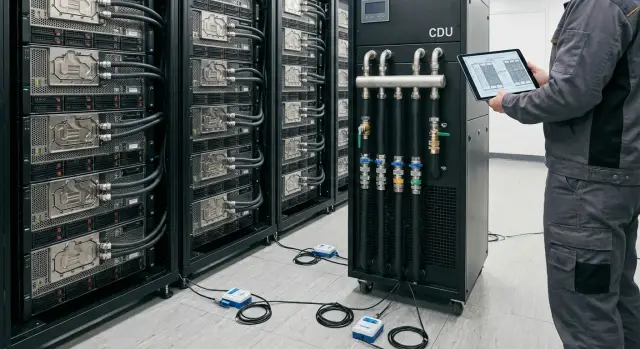
Then estimate the mid-system components: CDU, pumps, redundancy, leak sensors, pressure and flow monitoring, and integration with monitoring. Only after that check on the floor plan where everything fits and how maintenance staff will reach it.
Final step: agree operating procedures—work windows, who replaces seals and filters, where spare parts are stored, and what to do on a night leak alarm. Without that, liquid cooling often looks great on paper but is hard to live with.
What to check in the room engineering
Liquid cooling can increase density only if the room accepts "water" as part of the engineering system. Mistakes here are usually costlier than extra fans in a rack.
Layout and space for equipment
Estimate where CDU, manifolds and piping runs will go. It’s important not only that they fit, but that there’s proper service access: filter replacement, valve work, draining and filling, lifting equipment.
If the room is active, walk the route like a technician: can you get to the CDU with tools without blocking aisles, and is there space to safely remove hoses without touching neighboring racks?
Safety, spills and emergency scenarios
Plan where spilled fluid would collect: drip trays, curbs, drains, floor coverings. Place leak sensors not just "in the room" but at specific locations: under CDU, under manifolds, at connections and near the routing entry points.
Key is the scenario "pumps stopped." On power loss some loops can overheat or trip on pressure. You need clear automation and human actions.
Check at minimum:
- CDU and pump power: redundancy, UPS coverage, behavior on transfers
- shut-off valves: locations, speed of isolation, who has access
- coolant quality: filtration, corrosion control and material compatibility
- coordination with ventilation: what remains air-cooled (memory, VRM, NICs) and whether airflow is sufficient
- emergency logic: alarms, cluster shutdown, notifications, recovery order
In integration projects (when integrators like GSE.kz assemble and support clusters) these checks are usually documented: loop diagrams, control points and a clear leak/pump-failure response plan.
Maintenance and operations: what changes for the team
Liquid cooling usually adds operational discipline. Air forgives small errors (dust, wrong airflow, open blanking). With liquid, routines matter because loops, connectors and sensors are part of critical infrastructure.
The most visible change is how you take a node out of service. The team needs a clear fast procedure: stop the load, isolate the branch, relieve pressure, carefully disconnect quick connectors, close plugs. Good practice is to keep a prepared service kit near racks (absorbent pads, plugs, labels, drain containers) and log every operation.
Inspection routines and consumables
Planned checks become regular and short but mandatory. Inspections look at mechanical loop condition as well as temperatures:
- connectors and seals for moisture and corrosion
- filters and coolant quality according to schedule
- pressure trends and stability
- hose clamps and strain-free routing
- clean heat exchangers and no airlocks
Also track consumables: O-rings, filters, coolant, sensors. Train shift staff not just on how to undo fittings but how to avoid introducing air into the loop and not to confuse supply and return lines.
Replacing a GPU without long downtime
Plan how to replace a GPU or board without shutting down the whole rack. In dense deployments this is often solved by segmenting the loop per chassis or node so a local section can be isolated.
Monitoring should include more than supply temperature:
- pressure differential as an early clog sign
- per-branch or per-rack flow
- return temperature
- leak alarms (pads, near connectors, at routing entries)
- trends, not only instant values
If working with an integrator and manufacturer, ask them to include these procedures in the ops manual and run a short training on a mock removal.
Common mistakes and pitfalls in liquid projects
Some treat liquid cooling as simply replacing noisy fans with pipes and exchangers. Most problems arise at the intersection of engineering, operations and rules.
A common mistake is forgetting the heat that remains on air. Even with GPU and CPU on liquid, servers still have VRM, memory, NICs, drives and PSUs. If airflow worsens or supply air temperature rises, those parts overheat first and you’ll see failures in unexpected places.
Another pitfall is an overly complex loop scheme with no clear servicing logic. Extra manifolds, nonstandard branches and mixed connector types make repairs slow. The more complex the hydraulics, the more important it is to decide which elements can be serviced live and which require a full shutdown.
A third issue is lacking emergency isolation and leak localization procedures. You need clear decisions: who decides what to shut off first, how to isolate a section, how to protect power and neighboring racks. Without this, a small leak becomes cluster downtime.
People also err with materials: coolant incompatibility with seals, metals and coatings causes corrosion, swelling or blockages. This may not show immediately, so require specs for compatibility and a single standard for components.
Check before procurement and installation:
- where leak, pressure and temperature sensors are placed and who sees them
- presence of drip trays, drains and a clear path for liquid removal
- access to rack rears and service aisles
- consistent connectors, hoses and materials across the project
- ability to service a node without stopping the whole row
A typical scenario: a rack is assembled but aisles remain as before. To replace a hose you must roll out a server and remove a neighbor, increasing the chance of accidental shutdowns. Design for serviceability rather than leaving it as a task for the on-call shift.
Quick checklist before procurement and installation
Before signing a spec for liquid cooling, pin down a few items on paper. This reduces surprises during installation and the first weeks of operation.
First, verify heat calculations not "on average" but for specific server configs and load profiles. In HPC the same node behaves differently under training, inference and mixed jobs. If unsure, include margin and confirm numbers via vendor specs and pilot measurements.
Next, ensure hydraulics aren’t designed "tight": supply and return temperatures defined, calculated flow per loop understood, and pump redundancy planned (at least N+1 for critical lines). Verify coolant compatibility with materials and filtration requirements.
Short procurement checklist:
- Heat load confirmed by node configs and target rack density.
- Loop parameters (temperatures, flow, pressure) agreed and pump/heat-exchange margin included.
- CDU, manifold and piping placement allows service access and safe routing.
- Leak protection includes sensors, automatic isolation and clear alert scenarios.
- Downtime risks assessed with recovery plans: who does what in the first 15, 60 and 240 minutes.
After the engineering checks, validate operations. With liquid, small tasks like topping up, changing filters and periodic checks become routine, not one-off events.
Agree with ops and contractors on:
- maintenance regimes: inspection frequency, top-ups, filters, coolant analysis
- spare parts and consumables stored locally, not "on request"
- procedures to isolate a node/rack without stopping the whole cluster
If an integrator handles the project, request that this checklist be part of acceptance. Projects by GSE.kz typically document control points for piping, sensors and procedures before commissioning so the launch has minimal unplanned stops.
Example scenario: expanding a GPU cluster in an existing server room
Background: an organization runs a small GPU cluster in 2–3 racks and needs to grow to 6–8 racks for new model training, but the room remains the same. Air cooling was acceptable while loads were short and infrequent.
The problem showed up during peak runs: racks hit kW limits and temperatures rose faster than the AC could handle. Practically this looked like fans going to max, increasing noise and dust, and GPUs reducing clocks because thermal targets couldn’t be maintained.
The chosen solution was manageable: direct-to-chip (D2C) for CPU and GPU plus a CDU on the loop. They kept logic simple: one loop for compute nodes, another for other equipment, so changes don’t affect the whole room. Monitoring covered supply/return temperatures, pressure, flow and leak alarms.
Before installation they checked not just racks but the room:
- where to place the CDU with service access
- how to route mains without crossing power cabling
- where to drain and how to handle service drains safely
- where to place leak sensors and feed them into the alert system
- how to ensure access to quick connectors
Success was measured by metrics: GPU frequency stability on long jobs, fewer heat-related shutdowns and predictability of maintenance (planned checks instead of emergency callouts). If an integrator is involved, make sure they handle both hardware selection and the intersection of engineering and ops. In Kazakhstan it’s often convenient to work with local vendors and integrators like GSE.kz so one team covers supply, commissioning and support.
Next steps: moving from idea to project
Start with input data, not server selection. You need numbers on heat (kW per rack and total), current layout and growth plan for 12–36 months. Fix room constraints early: available electrical capacity, redundancy, space for piping, noise limits and allowed downtime for installation.
Compare cooling options as you would live with them in operations. Often the winner isn’t the most "efficient" on paper but the one with clearer maintenance and faster recovery after incidents. Consider spare parts availability, lead times, compatibility with chosen GPU servers and who will actually service the system locally.
A simple plan:
- collect the cluster’s heat profile and expansion forecast in racks and kW
- choose 2–3 cooling architectures and evaluate service, leak risks and staffing needs
- specify room engineering requirements (power, redundancy, monitoring, water treatment, drainage, service zones)
- prepare operating procedures before procurement: who does maintenance, what’s an incident, what spares are kept
- compile everything into one document for tender or procurement: scope, timelines, work stages, acceptance criteria
Fix engineering and operational requirements early. Otherwise you may get a perfect rack that doesn't fit the piping, exceeds UPS loads or requires skills the team lacks.
For large or time-sensitive projects consider turnkey integration: site survey, GPU server selection, infrastructure, deployment and 24/7 support. For organizations in Kazakhstan this can be done with local partners like GSE.kz: the company offers S200 servers and data center infrastructure expertise, helping to align hardware, engineering and support in one plan. gse.kz