Isolated network contours on a single workstation: how to separate
Isolated network contours on a single workstation: physical and logical separation schemes, blocking routing and bridging, and a set of tests to verify leaks.
What “two contours” on one workstation means
When people talk about two isolated contours on a single workstation, they usually mean two networks with different rules. For example: an internal corporate contour (documents, accounting systems, medical data) and an external contour (internet or contractor network). The idea is that each contour enforces its own access rules and traffic exchange between them is forbidden or allowed only through designated control points.
It’s important to distinguish “two cables” from real isolation. Two cables plugged into one PC do not guarantee anything by themselves: the operating system can route traffic between interfaces, accidentally create a network bridge, or share the internet connection. Some applications also pick a different path than expected. Isolation means that even with user mistakes or standard OS settings, traffic between contours is impossible.
Typically business and security teams need a result that can be verified and maintained:
- access to required resources in each contour without unnecessary “holes";
- prohibition of data transfer between contours that bypasses policy;
- control that updates, antivirus and remote support happen only via allowed channels;
- logging: who connected, when and from where, and which attempts were blocked;
- manageable configuration so settings don’t break after updates or hardware replacements.
In many organizations (especially in government, finance, healthcare, education) requirements usually boil down to three ideas: separate networks by criticality, minimize exchange paths, and provide manageability that can be verified. So “isolated network contours on one workstation” practically means not convenience, but demonstrable absence of unauthorized routes between networks.
Where leaks between contours come from: a short threat model
When a workstation has two contours, leaks more often come not from a “hacker” but from accidental connections between networks. It’s useful to decide in advance what you are protecting: packets themselves, access to internal resources, or data a user can carry out to the external world via applications.
The most common source of problems is an unintended physical “bridge.” It appears when, in addition to two wired connections, Wi‑Fi is enabled, a USB modem is plugged in, or a smartphone is used as an access point. For a PC this is another interface that can become a bypass between contours or provide internet where it shouldn’t.
Next are risks at L2 and L3. Even without explicit routing, a contour can be revealed by management traffic. DHCP may hand out wrong parameters, ARP may indicate neighbors, and incorrect routes or enabled NAT can turn a workstation into a mini‑gateway. Sometimes it looks harmless: “printing just started working,” but in fact one contour gained access to another segment.
At the application level leaks are even simpler. Email, messengers and cloud services move files “by themselves,” especially if the user is logged in with the same account in both contours. Small conveniences are dangerous too: shared clipboard, browser sync, password managers, automatic upload of documents to corporate cloud storage.
A leak is not only about direct file transfer. In practice the following signs are alarming:
- DNS requests and attempts to reach external domains from a closed contour;
- access to resources of the “wrong” network (file shares, RDP, databases);
- routes appearing between subnets or unexpected NAT on the workstation;
- shared credentials and tokens that grant access from the external environment;
- any packets between contours, even if “just management traffic.”
Example: an employee works in the internal contour, and internet is provided via a smartphone over USB. If the PC has connection sharing enabled or automatically creates a bridge, internal addresses can start to “shine” externally via DNS and routing. For isolation requirements this is already enough to consider the scheme broken.
Physical separation: when two devices are simpler than one PC
If the goal is “isolated network contours on one workstation,” the most straightforward and verifiable approach is to physically separate contours onto different devices. This reduces the risk of an accidental bridge and simplifies audits: fewer settings and fewer hidden dependencies.
The most direct option is two separate PCs: one used only in the internal contour, the other only in the internet (or other external) contour. This costs more in hardware and space, but is easier to explain to auditors and easier to support.
A common compromise is two physical devices with a shared set of peripherals via a KVM switch. The user presses a button and sees either one PC or the other. It’s important to choose a KVM without “smart” network functions and without a shared USB hub that could pass through unexpected devices. In strict regimes shared audio, shared USB drives and even a shared printer are sometimes prohibited.
A third option is a thin client and two independent remote sessions on different servers/VDI instances, each in its own contour. This is convenient for support and accounting but requires discipline on the infrastructure side: separate gateways, separate accounts, prevention of clipboard/file copy between sessions, and print control.
Physical separation usually wins in audits and investigations but loses in cost and user convenience (users will try to find ways to transfer files). In organizations that need on‑site support and transparent supply chains, predictable workstations and clear service contracts are often chosen so incidents can be resolved faster.
Physical separation is typically mandatory if:
- regulators or internal security require “separate devices only”;
- classified, medical or payment data are processed in the isolated contour;
- any transfer channels (USB, printing, clipboard) are forbidden;
- you cannot guarantee control of OS settings on the workstation;
- regular checks are expected and the most provable option is required.
Simple example: accounting uses an internal system, while mail and web are on a separate PC. Even if the user makes a mistake, they physically cannot join the networks by changing OS settings.
Physical scheme on a single PC: two NICs and separate switching
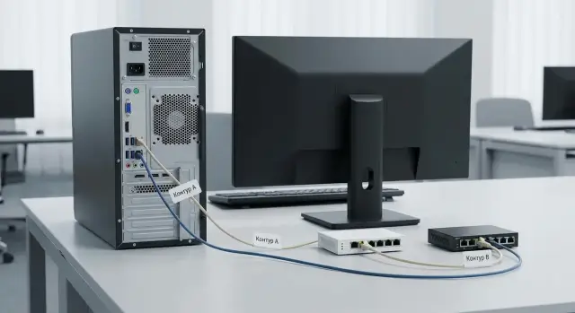
If you must implement isolated contours on a single workstation, the clearest physical option is two network cards (NICs), each connected to its own switch. Crucially, those switches must not be connected via uplinks and must not belong to the same L2 domain.
The logic is simple: NIC‑1 serves internal contour (corporate network), NIC‑2 serves the external contour (internet or guest segment). Separation relies on cables and switching rather than PC configuration, so it is easier to verify.
To make the scheme truly “hardware‑enforced,” do the following:
- connect NIC‑1 to a port on switch A and NIC‑2 to switch B (preferably in separate racks or at least on different patch panels);
- install two separate wall outlets (or two separate ports), and label patch cords at both ends: at the outlet and in the rack;
- document switch ports assigned to the workstation and record them in the switching diagram;
- forbid any shared L2 devices: no unmanaged mini‑switch under the desk, no shared docking station‑adapter, no “splitters”;
- verify there is no accidental physical link between the switches (including spare cables in the rack).
Treat Wi‑Fi as a second contour only as an exception. It’s harder to control and audit: you can accidentally connect to the wrong SSID, access points can be moved, and the radio channel cannot be checked as transparently as wired cabling. If Wi‑Fi is required for one contour, it’s better to have a separate Wi‑Fi infrastructure (dedicated APs and separate wired backhaul), not the same SSID used by another contour.
To make the scheme verifiable, document at least: which NICs (by MAC) correspond to which contour, outlet and patch panel port numbers, switch port numbers and cable labeling rules. In practice this fits on one sheet: “PC — outlet — patch panel — switch — port,” with date and responsible person.
Logical separation: VLAN, ACL and traffic control
Logical separation helps keep two contours on the same cabling infrastructure, but remember: VLAN is not the same as physical isolation. VLAN protects against mistakes at the switch level but won’t help if someone plugs a port into the wrong VLAN, configures a trunk to the workstation, or introduces a device that starts routing traffic.
A practical approach: assign a VLAN to each contour and make the workstation port an access port in a single VLAN (untagged). If a PC has two NICs, connect them to two access ports in different VLANs. A trunk to the workstation is almost always an unnecessary risk.
You also need border control: ACLs on L3 switches or firewall rules. The idea is simple: even if routing exists somewhere, traffic between contours should be denied by default and allowed only by explicit exceptions. Common blocks include:
- any connections between contour subnets (deny any‑any between VLANs);
- discovery and management protocols unless needed (LLMNR, mDNS, NetBIOS);
- access to DNS and proxy of the other contour;
- network equipment management from user VLANs.
A separate topic is “trusted services.” If contours are truly isolated, they need separate DNS, separate proxies and, if necessary, separate authentication domains (or separate zones/controllers). Otherwise a shared service becomes a pivot point enabling movement between contours.
On infrastructure side it’s safer to separate contours by VRF or even by separate routers. VRF keeps independent routing tables so contours won’t “see” each other even by mistake.
Main limitation: don’t rely on a single VLAN checkbox or a single inter‑VLAN deny. Protection must be layered: correct VLANs, strict ACLs, separate services and minimal exceptions documented as rules, not habits.
Blocking routing and bridges: what must be turned off
Even with cables correctly separated, leaks often appear due to OS or virtualization features that silently forward traffic between interfaces. It is important to establish in advance: the workstation is not a router or an access point.
On the OS: remove anything that “glues” interfaces together
First check that IP forwarding between network cards is disabled and there are no services doing NAT or internet sharing. This applies to both IPv4 and IPv6: IPv6 is often enabled by default and can create unexpected paths.
Minimum set of prohibitions to confirm:
- IP forwarding disabled for IPv4 and IPv6;
- no Network Bridge between adapters;
- Internet Connection Sharing (ICS) and any “share network” modes disabled;
- no local NAT, VPN in gateway mode, or proxy listening on both interfaces;
- no fallback where the OS switches outbound traffic to the “wrong” interface due to route metrics.
Practical example: an employee connects internal network and internet, then enables a mobile hotspot or ICS to give internet to a second device. The workstation becomes a bridge between contours.
On switches and virtualization: forbid unexpected bridges
On the switch side, a port for each contour should be configured so the station cannot act as a network device. Helpful port policies include MAC address limiting, DHCP spoofing protection, and disabling features not needed for an endpoint role.
If the PC runs virtual machines, virtual switches are another risk: a bridge mode can connect two physical NICs through a vSwitch. Rule of thumb: virtual networks for each contour must be separate, with no bridge between them and no shared management adapters. For corporate workstations (for example in integration projects) it’s better to enforce restrictions by policy rather than rely on the user.
How to configure: step‑by‑step
It’s easier to configure following an order: rules first, then hardware and network, then OS and applications. This makes it easier to prove contours do not intersect.
Work order
-
Define requirements. Describe for each contour which subnets and services are allowed, and which channels are strictly forbidden (for example, internal contour cannot access the internet, shared DNS/proxy/file exchange are forbidden).
-
Create a physical diagram. Record which NIC goes where, which cable and which switch port. If policy requires maximum separation, use separate switches (or at least separate ports and VLANs) and disable Wi‑Fi, Bluetooth and modems when not needed.
-
Configure the network: VLAN/ACL/firewall. Separate contours by VLANs and block any traffic between them with ACLs. Important: there must be no route from A to B on the L3 switch, firewall, or the PC itself. If any L3 exists, verify inter‑VLAN routing is disabled.
-
Configure the OS. Ensure IP forwarding, network bridge, ICS/internet sharing, and unnecessary virtual adapters (VPN clients, Hyper‑V/VirtualBox switches) are disabled. Separate network profiles and local firewall rules per interface. Each NIC must have its own “world” with no backup routes via the other card.
-
Restrict applications. Separate DNS (or block external DNS in the protected contour), configure proxy only where allowed, and enforce USB and file exchange policies so workarounds don’t become bridges.
What to hand over for security acceptance
Prepare a short evidence package: port and VLAN diagram, ACL/firewall rules, routing table dumps from the PC, test results (ping/traceroute, attempts to access forbidden subnets), and a test report with date, responsible persons and configuration version.
Example scenario: internal contour and internet on one workstation
An employee must work with internal documents (file server, ECM, internal mail) but sometimes browse the internet for references, updates and communication with external contractors. The task is to ensure internal resources cannot go out and internet cannot reach internal addresses.
The internal contour is connected to a dedicated switch or port that sees only corporate resources. On the workstation that NIC usually has no default gateway and DNS points only to internal servers. Then traffic to the outside simply has no route. Additionally, network equipment enforces rules so the internal segment cannot access the internet even if the PC is misconfigured.
The external contour is provided via a separate interface (e.g. Wi‑Fi or second port) with internet access. There, gateway or PC rules block access to internal subnets and internal DNS. If the user tries to open an internal address from the browser in the external session, the connection will not be established.
How this looks to the user:
- two separate sessions: work documents in the internal session, browser for the internet in the external session;
- or two profiles/two virtual machines: “Corporate” and “Internet”, with file transfer between them forbidden or tightly restricted;
- separate apps by purpose: corporate messenger and file client only in the internal contour, public mail and websites only in the external contour.
To make testing possible, keep artifacts:
- diagram: which ports, which interfaces, which subnets, where blocks are applied;
- configuration snapshots: routing table, DNS settings, firewall rules;
- test results: pings/traces to internal addresses from external session (should fail) and attempts to reach the internet from internal (should fail).
This scenario is common in government and large companies: workstations connect to a “clean” internal segment while internet is provided separately with no cross‑network rights.
Tests that confirm absence of leaks
Checks are easier if you first verify settings, then try to break isolation at L3 and L2, and finally confirm with passive observation.
Quick configuration checks
On each interface verify IP address, mask, gateway and DNS. A frequent cause of leaks is an extra gateway on the second interface or DNS serving both contours.
Next inspect the routing table. It should not contain routes to “foreign” subnets except explicitly allowed ones (if any). Ideally the isolated contour has no default route.
Short active test set:
- ping forbidden subnets and addresses in the other contour (expect timeout);
- traceroute to the same addresses (expect no route or early drop);
- attempt to connect to typical ports (80/443/445) in the other contour (expect refusal or timeout);
- DNS check: query a name resolvable only by the other contour’s DNS and ensure there is no response;
- L2 check: unplug and replug cable, request DHCP renewal, and ensure the address is not given from the other pool.
Passive verification and evidence collection
Capture traffic on each interface and look for unexpected packets: DHCP/ARP from another contour, DNS queries to an external resolver, or broadcast announcements that shouldn’t appear.
Example: on a dual‑NIC workstation capture on the internal interface. If you see DHCP replies from the internet switch or DNS queries to a public resolver, isolation is broken.
A successful test is repeatable: forbidden targets are unreachable, routes do not appear after reboot, DHCP and DNS remain contour‑specific. Attach ipconfig/ifconfig outputs, routing table, ARP table, ping/traceroute results and short capture extracts (a couple of minutes) with timestamps and interface names to the report.
Common mistakes and hidden “bridges”
Even with contours configured, leaks most often come from conveniences someone enabled out of habit. The OS tries to “help” and silently links interfaces.
The most common mistake is enabling internet connection sharing or creating a network bridge. In Windows this can appear as an accidental “Network Bridge” or ICS turned on. One interface starts sharing the connection to another and the two contours are no longer independent.
Equally sneaky is the “third channel” people forget: Wi‑Fi, Bluetooth PAN, USB modem or a phone in modem mode. Someone unplugged the cable but the wireless interface remained active and became a backup path. This happens often on laptops and all‑in‑one machines.
Things that typically create hidden bridges between contours:
- the same DNS or proxy serving both contours, allowing requests to go “the wrong way”;
- a VM or container with two adapters that starts forwarding between them;
- an admin adding a “temporary” route for testing and forgetting to remove it;
- NAT/routing enabled on the host to quickly “get internet”;
- no acceptance test, so the scheme works only by sight.
Example: in accounting a workstation has one port to the internal contour and another to the internet for updates. If connection sharing is enabled on that machine, internal devices suddenly get external access through it. Formally nothing else was connected, but contours are linked.
How to spot the problem quickly
Start with visual signs: a bridge appears, sharing is enabled, wireless interfaces active, VMs have two network connections.
Then check basics on the PC:
route print
ipconfig /all
Look for unexpected default gateways, routes to foreign subnets, and DNS servers that should not serve both contours. Without an acceptance test such errors are easy to miss.
Checklist and next steps: how to lock the result
Before commissioning the workstation, it’s important not only to set up two contours, but to record exactly what was done. This saves time during checks and reduces the risk that isolation “breaks” after updates or equipment changes.
A quick pre‑deployment checklist:
- physical: cables and ports labeled, each contour goes to its own switch (or strictly designated ports), no stray patch cords nearby;
- network: each interface has only its own gateway and DNS, no extra routes, auto‑connect to Wi‑Fi and Bluetooth disabled if not required;
- OS: routing and network bridge disabled, internet sharing prohibited, firewall policies per interface verified;
- applications: updaters, remote agents and cloud clients run only where allowed and cannot see the other contour;
- test: control pings/traces and access checks for typical resources in each contour.
After configuration collect the acceptance package for audit: connection diagram, list of MACs and switch ports, snapshots of routing tables, network adapter status, firewall rules and test results (command logs or reports). Store it with date and responsible person.
Regular checks (especially after OS updates, switch replacement or relocation): repeat basic isolation tests and compare routes with the “golden” baseline, ensure no network bridge or new virtual adapters appeared, verify no extra default gateway. Also verify switch ports and VLAN/ACL settings have not changed, and review security logs for unexpected activity.
If formal requirements, complex VLAN/ACL rules and acceptance tests are needed, involve a system integrator. When local support and predictable deliveries matter, these tasks are often delivered turnkey with workstations and service: for example, through GSE.kz (gse.kz) as a vendor and integrator with 24/7 technical support.