InfraWorks for road concepts: GIS and Civil 3D, LOD, alternatives
InfraWorks for road concepts helps quickly create route alternatives, link GIS and Civil 3D, manage LOD and prepare materials for approvals.
Why use InfraWorks at the road and masterplan concept stage
When a road or masterplan concept starts, the same problems almost always appear: data are scattered across sources, basemaps are assembled manually, and clarifications arrive daily. The team spends time not on decisions but on creating a “common picture” and rebuilding it after every change.
InfraWorks helps quickly assemble an easy-to-understand 3D model of the site and start testing ideas while the project is still flexible. At this stage speed and clarity matter more than perfect accuracy for every element: how the route fits the terrain, what happens to visibility, crossings and levels if you shift an alignment or change direction.
Early on it's useful to quickly check rough corridor geometry, potential interchanges and crossings, conflicts with watercourses, existing roads, buildings and protected zones, as well as principal levels and the order of earthworks. Plus — 3D visualization often resolves half the questions at early approvals.
A typical task is to choose one of three bypass options. In InfraWorks you can sketch alternatives, compare length, slopes and terrain “hot spots,” and present that at a meeting without weeks of drawing preparation.
It’s important to keep the responsibility boundary. InfraWorks does not replace detailed design: pavement structure, precise surfaces, complex nodes and documentation are normally done in Civil 3D. A practical scheme is: InfraWorks for quick direction choice and risk checks, Civil 3D for detailed design and issuance.
If your organization already has an integrator supporting the Autodesk stack (for example, GSE.kz), it’s best to agree on exchange and model update rules up front. Then the concept moves to the next stage without losses.
What data to prepare before import
To make InfraWorks work quickly, clarity of source files is more important than their visual polish: where things are, what units, which coordinate system and what simple attributes objects have. A good set of inputs saves hours looking for offsets, reassembling and manual fixes.
For a start, a minimal GIS context is usually enough: terrain (DTM/DEM or contours), hydrography (rivers, channels, water bodies), existing roads, administrative and project boundaries, land use or functional zones. If something is missing, it’s better to leave a gap than to mix in an outdated layer and then argue during approvals.
A separate topic is the coordinate system. Agree on it before import and record it in one place: name, EPSG (if available), units (meters) and vertical datum. A common story: Civil 3D and GIS live in different systems and the model “moves” by tens of meters. A simple test before loading: pick 2–3 control points (street intersection, bridge, plot corner) and check that coordinates match for all participants.
There shouldn’t be “every attribute at once.” For concept work useful attributes are those that speed up variant comparison: road class (arterial, street, access), pavement, speed limit, access restrictions, approximate lane count. For land — zone type and use restrictions.
Request in advance the data that most often “break” the concept at a late stage: utility routes (at least as lines and manholes/chambers), protected and sanitary zones, red lines and planned right-of-way corridors, flood zones and water protection strips, and key constraints (railways, viaducts, crossings).
A simple guideline: if you can explain on one screen why a variant avoids a protected area and stays outside right-of-way limits, then the data are sufficient for initial decisions.
Building a basic InfraWorks model from GIS
A basic model lets you quickly see the real site and avoid arguing about minor details. For concept work this means a simple 3D scene: terrain, water, coverings, buildings as masses and reference lines. The sooner you assemble the base the easier it is to compare route options.
Import is usually done in one of three ways:
- Model Builder — convenient for a quick background, but treat the data as draft.
- Direct file import (SHP, GeoTIFF, LandXML, etc.) — more control and repeatability.
- Connecting data sources — useful when GIS layers are updated and you need current layers.
Start with coordinates and elevations. Load terrain first (DEM/points/surface) and immediately check vertical datum, units (meters) and base level. Then add water bodies and channels, then coverings (roads are better as polygons, not just decorative lines), and only after that add buildings and zones (settlement boundaries, sanitary protection zones, protected areas).
To keep the model tidy, agree on simple rules: a single project prefix, clear layer names (for example, GIS_Roads, GIS_Water, GIS_Buildings) and a split between “source data” and “working edits.” That way you can always tell what came from GIS and what was manually adjusted.
A quick quality check takes 10 minutes but saves days:
- no holes or depressions in the terrain, especially at edges;
- buildings and roads don’t float above or sink below the ground;
- layers align coordinate-wise, no shifts of hundreds of meters;
- heights are read correctly (meters not confused with feet);
- objects weren’t duplicated after re-import.
If the project is for a public client, it’s useful to fix the layer structure and source formats in advance. This simplifies approvals and model handover, including via an integrator like GSE.kz.
Pipeline with Civil 3D: exchange and updates
At the concept stage you don’t need to bring everything into InfraWorks. The goal is to quickly check an idea, see terrain and building-related risks and create a few variants. Precise geometry, levels and schedules usually appear later in Civil 3D. A good pipeline makes concept work fast and detailing accurate.
Initially it’s often enough to transfer from Civil 3D those elements that set route logic and terrain reference: surfaces (existing terrain, sometimes a draft design), alignments and control points, longitudinal profiles (existing and draft if available), and corridors only when a rough volume or width estimate is needed. Key objects usually include right-of-way boundaries and bridge crossings as simple solids or lines.
Next, agree where the “source of truth” lives. A practical option: geodata and base surfaces are the reference, and alignments and profiles fall under Civil 3D control once a variant is deemed viable. InfraWorks remains a presentation and comparison front-end, not the only place for edits.
Typical cycle: sketch alignments in InfraWorks, pick 1–2 strong variants and export them to Civil 3D via an exchange format (for example, IMX or LandXML, depending on what you transfer). In Civil 3D the variant is refined to standards, profiles are clarified, a corridor is added, and then the conceptual model is updated to compare changes on the same base.
To avoid variants being overwritten, set a simple versioning rule upfront: each variant is a separate file set and name (A, B, C), record date and a short comment, import updates as new sources during comparison, and define who may change alignments and profiles.
Example: Variant B obtained a gentler profile in Civil 3D. In InfraWorks you update only the alignment and profile, leaving the background and existing terrain untouched. At the review it’s clear that the solution changed, not the model base.
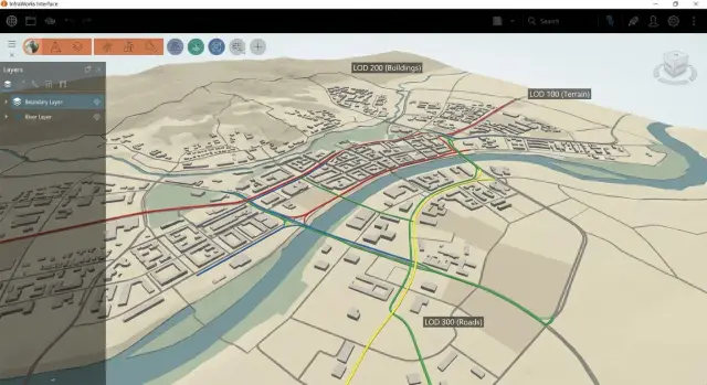
Levels of Detail (LOD) without extra work
LOD in concept work is not about prettiness but about answering questions: where the road will go, how it will sit in the terrain, where it conflicts with buildings and utilities, and approximate earthwork and structure costs. Anything that doesn’t help make a decision now is better postponed.
A simple rule: first build plausible geometry, then plausible appearance, and only refine details if they actually affect the choice.
LOD for the road: what’s enough at concept
Early on an alignment with clear parameters for speed and radii, a longitudinal profile with slopes and an approximate corridor (typical cross-section) are usually sufficient. Junctions and interchanges are better represented as understandable nodes with dimensions and space, not fully calculated ramps with markings and pavement layers.
To avoid drifting into details keep a short list of required parameters: the alignment and key points (turns, transitions, intersections), the profile and limiting slopes, 1–2 typical cross-sections, a high-level earthworks estimate and a list of conflict points (watercourses, railways, dense buildings).
LOD for the surroundings: show intent, not details
Collect the surroundings as masses: buildings as volumes, green areas as polygons, drainage as main flow directions, bridges and overpasses as envelopes and levels. This shows where structures are needed without spending time on construction design.
To keep the model responsive simplify sources: generalize contours in GIS and remove small polygons, and don’t pull unnecessary small lines and detailed surfaces from Civil 3D. If you compare three bypass variants, use the same typical cross-section and a single set of assumptions, changing only the alignment and nodes. Then comparison is fair and fast.
How to quickly create and compare route options
Variants come faster when you first define a corridor of possible passage and then draw alignments. For this the model must include terrain, water, buildings and key constraints (protected zones, red lines, right-of-way strips). Then a draft alignment is already “in reality” rather than a pretty line you have to justify later.
A practical approach: create 2–3 rough alignments with different logic rather than one “perfect” one. For a bypass that often looks like: Variant A closer to the city (shorter but more intersections), Variant B further out (longer but fewer conflicts), Variant C a compromise through freer land.
For conceptual comparison a few indicators understandable to both engineers and clients are enough: length and approximate travel time (a proxy for convenience), slopes and risk zones, number and type of crossings (river, rail, highways), rough earthwork volumes (“a lot or a little”), conflicts with restrictions.
Tackle the tight spots separately as mini-scenes. Rivers and railways often immediately separate variants into “needs a bridge/viaduct” and “can use existing crossing.” In dense urban areas highlight zones with high risk of land acquisition or utility relocations even if details are still missing.
To make a variant explainable to non-engineers, present it as a short story: objective, key decisions and trade-offs. Usually one top view with the corridor and labels for problem areas, 2–3 perspective views for complex sections and a short table “what we gain, what we lose” are enough.
If the concept is for a public client or large organization, agree the comparison format and deliverables with the integrator team in advance. At GSE.kz, for example, they often request a single template of indicators and scenes so the chosen variant is easier to hand over for further design.
Common mistakes and model pitfalls
InfraWorks works well if you keep the model clear and lightweight. Most problems arise not from the tool but from small details: coordinates, heights, excessive data and version chaos.
The most common mistake is poor georeferencing. When some data are in WGS84, others in a local system, and someone imports a basemap “as is,” an alignment visually shifts and levels lose meaning. This is often noticed late at a presentation: the road cuts through buildings or shifts away from cadastral boundaries.
The second trap is premature detailing. In concept you don’t need to act as if you’re already in detailed design: curbs, stormwater, millimeter slopes and detailed constructions. That consumes time and kills variant generation: any alignment change becomes a rework.
The third issue is importing “everything” from GIS: dozens of layers, heavy polygons, duplicate objects, 3D trees and detailed buildings. The scene then slows down even on a good machine. Keep a minimal set that answers concept questions: terrain, hydrography, roads, constraints and key objects.
Another problem is lack of versioning rules. If one person updates the surface, another edits the alignment, and a third changes the basemap, you quickly lose track of what was agreed. Assign responsibilities, fix change rules and save versions before meetings.
And of course heights. A surface may be in meters while some objects have zero levels or use a different vertical system. This creates breaks: a bridge “in the air,” ramps sinking, buildings submerged.
Before a demo do a short check: verify coordinate systems and units for all sources, check 2–3 control points for elevation, hide unnecessary layers and evaluate smoothness, ensure key objects sit on the surface, and lock the model version with a list of applied edits.
A simple example: the team prepared two bypass variants, but at the presentation one seemed better only because the surface was old while a new DEM was loaded in a different file. A few minutes checking elevation control points saves hours of argument.
Quick checklist before a presentation and approval
Before meeting a client it’s important to remove small surprises that damage confidence in the model. People expect simple answers at a presentation: where the route runs, what happens to the terrain, and whether the numbers are trustworthy.
First check basic geometry: take a couple of control points (intersection, bridge, block corner) and confirm the model matches known coordinates and elevations. Also verify units: metre/foot mistakes are often noticed during presentations.
Then review terrain in problem areas: watercourses, embankments, interchange zones. Look for spikes, steps and holes. If the surface looks odd in one place, it will stand out even more on slides.
Presentation checklist:
- Coordinates and units confirmed at 2–3 known points.
- Terrain visually smooth without spikes, breaks or sharp ledges.
- Layers named by meaning, unnecessary ones hidden, groups toggled with one click.
- Variants built from the same base, assumptions (speed, slopes, pavement type) recorded.
- Exports and materials prechecked: label readability, scale, set of views and legend.
Finally run a 5-minute rehearsal: open required views, sweep camera through key points and ensure nothing lags or distracts. If the model will be handed to Civil 3D, agree in advance what is the source of truth: alignment, surfaces or corridor.
Example scenario: 3 bypass variants for a masterplan
The task: propose a bypass around a city and quickly agree the corridor direction. Start with a simple base: city basemap (streets, buildings, red lines), a digital terrain model, settlement boundaries and the working area, and the existing road network. That is enough to build a 3D picture and compare options.
Then create three route corridors with the same basic rules (speed, minimum radii, typical cross-section).
Variant A runs closer to the city and opts for areas with gentler terrain. It often wins on earthwork volumes and risk but may be longer and require more connections.
Variant B is straighter to reduce distance and travel time. It often hits hard constraints: needs an interchange on a major road and a river crossing (bridge or viaduct). At concept stage it’s important to show where expensive elements will appear and what to check: levels, clearances and water protection restrictions.
At the stakeholder meeting show differences with the same set of materials: 2–3 fixed 3D views per variant (entries, intersections, critical spots), the corridor diagram with key nodes and ties to the existing network, a profile summary (where rises/descents and cut/fill occur), 3–5 main risks and simple metrics (length, number of crossings, approximate earthwork volumes).
After discussion document not only the chosen variant but also the decision boundaries: which variant was accepted and why (2–3 reasons), assumptions on terrain, pavements and constraints, data to refine (geology, utilities, hydrology, red lines) and nodes to detail next (interchange, bridge). This prevents disputes later: everyone knows what was agreed at the concept level and what goes for further checking.
Preparing deliverables and handing over for further design
So the concept doesn’t remain a pretty picture, agree in advance how you will hand results for the next stage: what goes for approval and what becomes the basis for detailed design. At concept it’s important to record not just visualization but measurable parameters to avoid arguments “by eye.”
Outputs typically include items that are easy to check and compare between variants: plan view with node labels, stationing and work boundaries; longitudinal profile for the alignment and 2–3 cross-sections at key spots; a parameters table (length, slopes, radii, minimum levels, estimated volumes); a couple of clear 3D views from the same points for all variants; and a short note on risks and constraints.
Prepare results so they can be reproduced after source updates. A simple practice: lock versions of source layers, use consistent naming (axis_variant_A, interchange_node_1), keep the same sheet templates and camera views. When DEM or GIS updates happen you don’t re-create the presentation — you recalc and re-export.
Transition to detailing is best done in stages so Civil 3D doesn’t receive “everything at once and nothing clear.” A common handover order: corridor (alignment, profile, typical cross-sections and parameters), earthwork boundaries and preliminary volumes, junctions and nodes, control points and surfaces for integration with the masterplan and vertical layout.
Treat related systems as constraints even if they are drafts: utility corridors, stormwater flow directions and outlets, bridge/viaduct envelopes (clearances, spans, restricted support zones). Mark them in the model as conflict zones and assumptions rather than risk losing a variant to a late collision.
Next steps: pilot pipeline and support
If the first model shows value, the next step is to turn scattered actions into a repeatable process. Failures usually come from agreements, not tools: which data are current, who updates them, where they are stored and rules for variant work.
Bring an integrator on board when the project becomes a team effort or “living” (data change weekly). Then define standards: GIS layer and attribute structure, naming of alignments and routes, unified coordinate system, Civil 3D import templates, access rights and change history.
Also design the software and infrastructure links: common storages, databases for source layers and a clear collaboration workflow so designers don’t keep desktop copies. Another common question is performance: conceptual 3D models quickly hit RAM, GPU and network limits.
If you need a single support contour, GSE.kz (gse.kz) often helps: select workstations and servers for your model size, deploy collaboration infrastructure, set up integrations and provide support so the team doesn’t stall before presentations.
A typical start is a clear plan: a pilot on one district or corridor (1–2 weeks), a project template (coordinates, styles, naming rules, source composition), an update regimen (who and how often updates GIS, Civil 3D and basemaps), rules for variants (how to record scenarios and what constitutes a review-ready version) and an agreed set of deliverables for handover.
This way the pilot pipeline becomes standard practice quickly and variant quality improves without extra manual rework.