Civil 3D Project Coordinate System: Settings Checklist
Step-by-step checklist for setting the Civil 3D project coordinate system so surfaces, alignments and underlays don't shift when exchanging DWG and LandXML.
Why surfaces, alignments and underlays start to “move”
Displacement in Civil 3D often looks like “magic”: yesterday everything matched, but after importing LandXML, attaching an Xref or inserting an underlay objects end up off. Usually it’s not a “Civil 3D crash” but that you are assembling a project from files with different settings.
Symptoms are almost always the same: a surface and an alignment diverge by meters or kilometers, an underlay lies at a different angle, a PDF or raster suddenly appears 1000 times larger (or smaller), and in one file “everything is correct,” but after attaching external data everything “breaks.”
Most often the items that “move” are surfaces (TIN), alignments and profiles, external DWG references, and PDFs/rasters. The reason is simple: these objects come from different sources, and each source carries its own assumptions about units and coordinates.
Why is everything fine in one file? Because within a single DWG all elements live in the same coordinate system and units, even if chosen incorrectly. Problems start at file boundaries: you attach an Xref, insert an underlay or import LandXML, and Civil 3D tries to match two “worlds.” If one drawing uses meters and a defined zone, and another uses millimeters and “no zone,” the result looks like an error even though it’s just mismatched settings.
Example: the alignment project was made in meters with a specified zone, but the topographic DWG arrived in millimeters without georeference. While each file is open separately everything looks fine. But when attaching as an Xref the surface ends up “far away,” and labels and profiles no longer match the real geometry.
Minimum terms: units, zone, elevations
Most displacements start not with surfaces or alignments but with basic concepts. If your team agrees on these once, work stops being a lottery.
Drawing units and source data units are not the same thing. A DWG may be in meters while the source (for example, XML or text coordinates from surveyors) may be in millimeters or meters but with different precision. The import succeeds without errors, but on screen everything is “in the wrong place” or “wrong scale.”
Local coordinate systems and national systems also differ in meaning. Local is a convenient “zero” and axes chosen for a site (often useful for construction). National is tied to the country/region system where coordinates make sense on a map and when stitching with other objects.
Zone in Civil 3D is the selection of a specific coordinate system and projection so the program correctly calculates positions, directions and transformations during import and attachment. If the zone is wrong (or not set), an underlay can “move,” and objects from another file will sit nearby but not match.
Elevations are trickier: plan (X, Y) may match while elevations (Z) float by decimeters or meters. Common causes:
- different vertical datums (for example Baltic system vs local benchmarks)
- geoid heights vs ellipsoid heights (GNSS)
- a local zero level used on site instead of the national network
- Z in meters in one file and accidentally in millimeters in another
Example: an alignment appears in the correct plan position, but the profile “dropped” by 1.2 m. Usually this isn’t a surface error but different elevation conventions between the source data and the project file. Before exchange, clarify: in which units X/Y/Z are provided, what horizontal and vertical systems are used, and whether elevations are local or national.
Preparing the file: template, basic settings and action order
Start not with importing data but with the correct base file. A common cause of shifts is a drawing assembled from “whatever was at hand”: random units, unknown zone, or no coordinate system assigned at all.
Create a new DWG from the required DWT. The template should have Civil 3D styles, units and the project coordinate system preconfigured. If you use a blank acad.dwt or an old “working” file, you almost guarantee different settings among exchange participants.
Then open Drawing Settings and set the base: Units and Zone. This is where Civil 3D “understands” in which units to calculate and which coordinate system to live in. Within the project keep one rule: one coordinate system for the entire exchange, no “this file in local, that file in WGS.”
A convenient order before loading surfaces, alignments and underlays:
- Create the DWG from the correct DWT.
- Set Units and Zone in Drawing Settings.
- Save the file and only then attach Xref, PDF, rasters.
- Then import LandXML or insert data from other DWGs.
- After import do a quick check of positions by control points.
Signs that the drawing actually has “no coordinates”: the zone isn’t chosen, coordinates of key points look “small” (like local meters from zero), and when an underlay is attached it flies far from the model.
If you imported a surface (for example from LandXML) into an old DWG and it landed “nearby,” often the culprit isn’t LandXML but the template and Drawing Settings. First fix the base, then re-import.
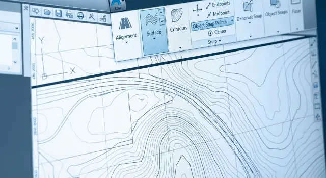
Steps in Drawing Settings: Units and Zone
When surfaces, alignments and underlays diverge, the cause almost always lies in two settings: Units and Zone. Check them before import and again before handing files over.
Units: what exactly counts as meters
With Units it’s important not just to pick “meters” or “millimeters,” but to ensure this matches how the objects were created and how external data arrives.
A practical rule: if distances between points are typically hundreds or thousands (for example 350.00), it’s usually meters. If typical values are 350000, that’s often millimeters. A units error gives “incorrect” scales when inserting DWG, PDF and rasters and looks like displacement.
Zone: the chosen coordinate system
Zone is the main switch that tells Civil 3D how to interpret X/Y and tie to a real place.
Check this step-by-step:
- Compare the Zone with the spec or source data (which coordinate system and zone is used).
- Make sure the Zone is set in the current DWG.
- Verify the zone wasn’t changed during the work. Even one switch can leave part of the objects “in another world.”
- Fix inside the team: one coordinate system and one set of units for all files, including underlays and LandXML exchange.
If the zone is unknown, stop and clarify with the data source. Guessing almost always ends with a displacement that is hard to track later.
Checking georeference: where the project is and how to verify
The first sign of georeference problems: the drawing “lives” near zero (0,0) rather than in real coordinates. If you Zoom Extents and objects are around the origin while expected X/Y should be six- or seven-digit numbers, the project is likely misplaced.
Check with 2–3 points that can be unambiguously identified: a benchmark, a station, a corner of the coordinate grid, a control point from the survey. It’s important to compare numbers, not just “does it look similar.”
Quick verification steps:
- Snap to a known point and compare X/Y (and Z if needed) with the schedule.
- Measure distance between two known points and compare to the reference (this quickly catches units errors).
- Check direction. North-up isn’t required, but axes must be consistent. A common trap is a rotated UCS or view.
- Evaluate elevations. If marks “flew” by hundreds of meters the cause is often a vertical system or units issue.
If the project is already “in the wrong place,” don’t move objects by eye. First freeze a reference point and the required coordinates, then choose one correction method for the whole file: either translate the entire contents by one vector, or set the correct zone and reinsert/reconnect data. After correction repeat checks by the same control points.
Surfaces: settings and checks before exchange
Shifts are especially visible on surfaces: points “land” incorrectly, breaklines break triangulation, elevations fall into a different range. Before exchange understand what the surface is built from (survey points, breaklines, corridor, another surface). The more dependencies, the higher the chance that something will be recomputed differently on transfer.
Before sending check the base in this order:
- do source units and drawing units match?
- are elevation ranges realistic (e.g., 120–350 m not 120000)?
- is the surface dependent on links/corridors that the receiver may not have?
- is a surface boundary defined so it won’t “spread” during recompute?
Copying a surface between files often brings surprises: in one drawing it may have been “correct” simply because the required settings existed there. In another DWG Civil 3D may interpret tolerances differently or apply a different scale.
After import check both the picture and the numbers:
- are there TIN spikes at edges?
- do min and max elevations match expected values?
- is a style enabled that immediately shows errors (contours, elevation labels)?
- does the position match reference objects (axes, survey points, outlines)?
A practical method: take 2–3 control points with known X, Y, Z and compare the surface elevation at the same spots. If discrepancies are tens or hundreds, units or elevations are almost always to blame.
Alignments and profiles: avoiding displacement and desynchronization
Two common alignment mistakes: where stationing starts and which direction the alignment runs. Even if the geometry seems right, stationing can be offset and the profile will no longer align.
Start with the start point: in alignment properties check the initial station (for example 0+000). Then check direction: if the alignment was built in the opposite direction stations grow “the other way” and the profile no longer matches expectations.
Separately check the link between alignment and profile. The profile should be linked to a specific alignment, not just a set of lines in profile view. When moving between drawings this link often breaks: the alignment is copied one way, the profile another, objects are renamed and Civil 3D loses the reference.
Quick checks before exchange and right after import:
- X/Y coordinates of alignment start and end points
- 1–2 key points (kinks, intersections, junctions) by coordinates
- stations at those points (the intersection should be at the expected station)
- profile linkage to the alignment and update on changes
Example: an intersection with an existing road “moved” by 20 m. Alignment start coordinates matched, but stationing began from 0+120 instead of 0+000 due to initial station setting. This is visible in a minute by comparing station and coordinates at one control point.
Underlays and external references: DWG, PDF and rasters without surprises
Underlays and Xrefs often “move” not because of geodesy but because of small things: different insertion units, wrong method of attachment, or an underlay someone once nudged “by eye.” Even the correct project coordinate system won’t save you if the external file was inserted with wrong units or scale.
Xref: Attach vs Overlay
Attach pulls nested references (if they exist inside the attached file). This can be useful but it’s easy to end up with duplicate underlays or unexpected shifts when exchanging. Overlay attaches only the selected DWG and doesn’t “pull the tail.” For assembling multiple files Overlay is often safer.
Before attaching check two things: insertion units in the current file and units in the external DWG. If one file is “in meters” and another “in millimeters,” the result will look like a 1000× scale difference rather than a simple offset.
PDFs and rasters have a different typical problem: they often arrive without reliable scale and are placed “approximately.” Later such a file enters the model and looks “moved.”
Quick checks:
- Xref attached as Overlay (unless nested references are needed)
- insertion units of current DWG and external match
- PDF/raster placed at a known scale (by grid, frame, or measured dimension)
- insertion point anchored to a clear reference
- rotation set numerically, not “rotated by eye”
Data exchange: DWG and LandXML, what to check before and after
When data “moves,” it’s usually not the file’s fault but how it was prepared and attached. Keep the rule: coordinates, units and zone are fixed once and not “tuned” manually.
DWG to DWG: what to clean and what not to touch
Before sending or receiving a DWG run Audit and Purge, remove junk layers, and ensure external references and underlays are either intentionally attached or removed. But don’t change Units “for neatness” and don’t move geometry to 0,0 if the file already has correct georeference. Any visual “fitting” will return as displacement on the next step.
LandXML: what is especially sensitive
LandXML most often causes problems with units (meters/millimeters/feet) and with understanding the coordinate zone. The most sensitive elements are surfaces (elevations and scale), alignments (PI coordinates, direction, stationing) and profiles (vertical marks and baseline).
To reduce risk, request along with the file:
- the coordinate system name (at least zone and datum, EPSG is better)
- horizontal and vertical units
- 2–3 control points with X/Y/Z and explanations
- the original DWG “as they have it,” without manual shifts
After import don’t trust the screen. Compare 2–3 control points: coordinates, distance between points and one elevation check (for example a benchmark). If any check fails, don’t continue until you find whether the discrepancy is in Units or Zone.
Practical example: received data and everything shifted
Typical case: you already have a georeferenced PDF placed correctly, and a contractor sends a DWG with a surface and alignment. You attach the Xref and see: the alignment moved by hundreds of meters, the surface hangs somewhere else, elevations don’t match.
To avoid arguing who is right, pick one “truth” and check everything against it. Usually this is 2–3 control points: axis intersections, building corners, survey control points, or alignment station marks. If none exist, agree with the contractor on a couple of coordinates (X, Y, Z) and record them.
Then follow order: set the project coordinate system before import and before attaching external references. Otherwise you’ll be treating symptoms.
A check that usually takes 10 minutes:
- Open an empty file from the correct template, set Units and Zone in Drawing Settings.
- Open the contractor’s file and determine in which units it is actually drawn (a typical sign of error is lengths 1000× larger or smaller).
- Import the surface and alignment only after units and zone match.
- Attach the PDF and compare by control points: is there shift, scale or rotation?
- If discrepancy exists, determine the type: constant shift (insertion point), scale (meters/millimeters), or rotation (axes/north).
Example: the PDF sits “correctly” but the alignment is offset by exactly 500000 in X. This often means the contractor used a different zone or exported without the correct coordinate system.
Frequent errors and traps that cause displacement
The most unpleasant shifts come from small mismatched settings between files.
- Mixed millimeters and meters. One file in mm and another in m = 1000× scale error on Xref or LandXML.
- Left the drawing “without a zone” then started attaching underlays and references. Without a zone you may accidentally see something that “looks right.”
- Changed the zone mid-project and didn’t rebuild objects. Part of the model remains in the old logic.
- Attached an Xref with wrong units and “corrected by eye” with Move/Rotate. It will look right on screen but return when updated.
- Copied objects between files without control points or numeric verification.
If something moved, first check basics:
- identical units (mm/m) in source and target files
- zone set before attaching underlays/Xrefs
- zone not changed during the process
- no manual “fitting by eye”
- 2–3 control points match X/Y/Z
Short checklist before sending and receiving files
It’s useful to run the same short checks before sending and immediately after receiving. Record numbers, not impressions.
-
In Drawing Settings verify Units and Zone (plan units, elevation units, chosen system/zone). If this doesn’t match source data, further checks are pointless.
-
Verify 2–3 control points: X/Y and elevation (Z). Check both plan and height.
-
Before attaching Xref, PDF and rasters check insertion units and scale. If an underlay arrives in the correct direction but wrong size, it’s almost always a units issue.
-
If LandXML was provided, import into a copy and compare key numbers: alignment start coordinates, characteristic surface elevation.
-
Assemble a transfer package: final DWG, all external references/underlays and a short memo (units, zone, vertical system, date).
If any control point fails after receipt, don’t fix by eye. Return to Units/Zone and the data source: correction at that level usually takes minutes.
Next steps: how to lock the process and avoid shifts again
One-off checks help, but shifts reappear when every participant has their own “correct” template and habits. The easiest way is to enforce a few rules: one project coordinate system, one set of units, and a clear exchange format (when to use LandXML and when DWG).
Make this a short one-page procedure and keep it with templates. Add control points as a mandatory step after each import and Xref/underlay attachment. If something doesn’t match, cancel the import and investigate immediately before the error propagates across profiles, labels and schedules.
For heavy projects (large surfaces, many corridors, underlays, point clouds) plan in advance where sources will be stored and what the team will work from. Shifts sometimes hide because someone disables part of the data for speed and later reassembles everything and gets a surprise.
An outside look at infrastructure and process can help. For example, at GSE.kz (gse.kz) they match workstations and servers to CAD load and assist with system integration so unified exchange rules are supported not only verbally but in daily work.
FAQ
Why do surfaces, alignments and underlays suddenly start to shift in Civil 3D?
Most often it’s not a “bug” but a mismatch of basic settings between files: units (meters/millimeters), assigned coordinate zone, or rules for elevations. Inside a single DWG everything can look correct, but when you import or attach Xref Civil 3D tries to reconcile different “worlds” and you see a shift, rotation, or a 1000× scale difference.
What to check in the first minute if everything “moved” after import or Xref?
Check two places right away: Drawing Settings (Units and Zone) in the current DWG and the actual units of the data you are importing or attaching. The quickest way to catch the error is to compare two known points: if the distance between them becomes 1000 times larger/smaller, it’s almost always meters vs millimeters.
How do Units affect displacement and why does a 1000× scale appear?
Units determine in which units Civil 3D interprets geometry and inserts. If one file is drawn in millimeters and another in meters, attaching them will produce a 1:1000 scale and look like a displacement. It’s better to fix units and re-import/attach than to Move items “by eye.”
Why is Zone needed in Civil 3D and what happens if the wrong one is selected?
Zone sets the specific coordinate system and projection so Civil 3D can correctly interpret X/Y and transformations when attaching data. If the zone is not set or the wrong one is chosen, objects can end up “nearby but not matching,” shifted by hundreds of kilometers, or rotated. Assign the zone before importing and do not change it mid-project without rebuilding data.
Why can the plan match but the profile or elevation marks “drop”?
Plan (X/Y) can match while Z values drift if sources use different vertical rules: different vertical datums, geoid vs ellipsoid (GNSS), or a local site zero instead of a national network. Another common mistake is Z values in millimeters. Agree up front which units are used for X/Y/Z and what vertical system is applied.
How to quickly tell that a drawing has no georeference at all?
Do a Zoom Extents and see whether the model sits near the origin (0,0) instead of real coordinates. Then check 2–3 control points numerically: snap to the point and compare X/Y (and Z if needed) with the survey sheet. If the numbers don’t match, don’t trust the visual and stop until you find the Units/Zone/elevation issue.
What to choose for Xref: Attach or Overlay so nothing shifts?
Overlay is usually safer because it doesn’t bring nested references and reduces the risk of duplicate underlays and unexpected dependencies during transfer. Attach pulls nested links (if present), which can be convenient but may introduce surprises. In either case, ensure insertion units and the coordinate base are consistent between files.
Why do PDFs or rasters insert “in the wrong place” or at the wrong scale?
PDFs and raster images often arrive without reliable georeference, so they’re easy to place approximately and later appear displaced in the assembled model. Best practice is to anchor the underlay to a known control, set scale and rotation numerically instead of by eye, and then verify by a control length or known frame/grid.
What typical causes of displacement occur when importing LandXML and how to detect them?
LandXML is sensitive to units (including feet) and to the interpretation of the coordinate system. The most sensitive elements are surfaces (elevations and scale), alignments (PI coordinates, direction, stationing) and profiles (vertical marks and baseline). Before import, set Units and Zone in the target file; after import, check 2–3 control points for X/Y/Z. If they don’t match, revert the import and resolve the discrepancy.
What to do if the project is already made but turned out to be in the wrong place?
Don’t Move objects by eye — that breaks consistency and will come back when links refresh. First pick a reference truth (2–3 control points) and determine whether the issue is a constant shift, a scale difference, or rotation. Then fix systematically: align Units and Zone and re-import/re-attach, or translate the whole drawing by a confirmed vector.
What common mistakes and traps cause displacements?
Common culprits: - Mixing millimeters and meters: one file in mm and another in m leads to 1000× scale errors. - Leaving the drawing without a zone and then attaching underlays. - Changing the zone mid-project without rebuilding objects. - Attaching an Xref with wrong units and then manually moving/rotating it to fit visually. - Copying geometry between files without control points or numeric checks. If things shifted, first verify base settings: same units (mm/m), zone set before attaching underlays/Xrefs, zone not changed during work, no manual eyeballing, and 2–3 control points matching X/Y/Z.
Short checklist before sending and receiving files
Quick pre-transfer checks to do before sending or right after receiving: 1) In Drawing Settings check Units and Zone (plan units, elevation units, chosen system/zone). If this doesn’t match the source data, further work is pointless. 2) Verify 2–3 control points: X/Y and elevation (Z). Check both plan and height. 3) Before attaching Xref, PDF or rasters check insertion units and scale. If an underlay arrives at the correct orientation but wrong size, it’s almost always a units issue. 4) If there is LandXML, import into a copy and compare key numbers: start coordinates of alignments, characteristic surface elevations. 5) Prepare a transfer package: final DWG, all external references/underlays and a short memo (units, zone, vertical system, date). If any control point doesn’t match after receipt, don’t fix by eye. Return to Units/Zone and the data source: fixes at that level usually take minutes.
Next steps: how to cement the process and avoid shifts again
Rules to lock in: - One project coordinate system, one set of units. - A clear exchange format (when to use LandXML vs DWG). - A one-page procedure kept with templates and a mandatory step of checking control points after each import/Xref. For large projects, agree in advance where sources will be stored and what the team will work from. Displacements sometimes hide because someone turns off parts of the data for speed and later reassembles everything. If needed, get an external look at infrastructure and process. For example, at GSE.kz (gse.kz) they select workstations and servers for CAD load and help with system integration so shared exchange rules are enforced not only verbally but in daily work.