Cisco Nexus 9300 for Data Centers: choosing cards, optics and validation checks
How to choose line cards and 25/100GbE optics for Cisco Nexus 9300 in a data center and how to run a pilot to validate FEC, CRC and buffers.
Where to start: data center requirements in plain words
Choosing Cisco Nexus 9300 for a data center should start not from a catalogue of modules, but from understanding real traffic. In most data centers the biggest bandwidth consumers are storage (especially at peaks), virtualization and backups. First identify where latency must be minimal and where predictability without loss is more important. Different traffic profiles expose FEC, CRC and buffer issues in different ways.
Next, count ports in simple blocks: how many server ports you need at 25GbE and how many uplinks you need at 100GbE. Don’t try to guess “five years ahead,” but allow a clear margin for rack growth and migrations. A common early mistake is to buy many 25GbE ports but skimp on uplinks, then hit congestion upstream in the fabric.
Also document physical constraints up front: distances between racks and halls, whether copper exists or only fiber, and what fiber type is already laid. This quickly narrows transceiver and cable options and reduces the risk of surprises at handover.
Write down the business requirements that truly matter: allowable loss, maximum latency for key services, and the required level of resilience (redundant uplinks, alternate paths, fast restarts). Not all applications are equally sensitive, and that’s fine.
Before procurement, resolve the basic items on paper: port capacity (how many 25GbE per rack and how many 100GbE between tiers), distances and medium (copper/fiber, fiber type and actual lengths), SLOs for quality (what is unacceptable: losses, latency growth, downtime) and growth scenarios for the next 12–18 months. Fine settings (which FEC to enable, where CRC will appear, whether buffers handle microbursts) are best validated with a pilot on your traffic rather than relying on generic diagrams.
If you don’t have time to develop a test methodology from scratch, a systems integrator can help formalize requirements and run a pilot so findings feed directly into procurement and scaling. In Kazakhstan such work is often handled by teams like GSE.kz — covering design, pilot and ongoing infrastructure support.
Line cards and ports: how to choose configuration for 25/100GbE
The first simple question when choosing a Nexus 9300: is it a fixed-port switch with a set number of ports, or a platform available in different port variants? People often call both “Nexus 9300,” but procurement and growth scenarios differ. With fixed ports you accept limits on speeds and uplinks up front. Configurable platforms let you tailor ports to topology, but avoid overpaying for unused ports.
When planning 25GbE, count not only servers but also which 100GbE uplinks you want on the leaf (ToR). Typical logic: servers use 25G, uplinks to spine are 100G. Then do the math: how many 25G ports remain once you allocate ports for uplinks, MLAG or service connections. Teams often see “48×25G” on paper but later discover many ports were consumed by uplinks and redundancy.
Look beyond raw port speeds: consider downlink/uplink ratio, breakout support and how your port plan fits the topology.
Oversubscription and real uplinks
Oversubscription is the ratio of total downstream capacity (to servers) to upstream capacity (to spine). If you connect many 25G servers but provide few 100G uplinks, you may run out of bandwidth at peaks. That isn’t always bad: VDI or office loads tolerate higher consolidation, but storage and heavy east–west traffic need margin.
Breakout and mixed speeds
Breakout is useful when a single 100G port can be split into several lower-speed lanes (for temporary connections or gradual port growth). But it affects port planning, cabling and which speeds can run simultaneously. Decide up front whether you’ll use a pure “25G to servers and 100G up” profile or a mix of speeds.
Before buying, verify compatibility with your ToR and core design: leaf–spine, paired ToRs per rack, separate storage zones and redundancy requirements. The same port count can behave very differently in a real design if you run short of uplinks, lack ports for inter-switch links, or hit mode restrictions.
To plan growth without overpaying, fix a minimum needed at launch and a sensible 12–18 month buffer. Answer questions like: how many 25G ports for servers now and after expansion; how many 100G uplinks per leaf given acceptable oversubscription; do you need breakout and which speeds must remain supported without changing cabling; how many ports are reserved for redundancy, inter-switch links and management. If you deploy for government or large enterprise, align the port plan with those responsible for design and the pilot. Projects run by GSE.kz typically start with this port math, then choose optics, FEC modes and test scenarios.
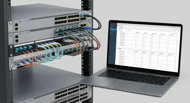
Optics and cables: typical choices for 25GbE and 100GbE
Optics and cable choices usually start with a simple question: is the connection within one rack, within a hall, or between halls? Distance and serviceability affect cost and how quickly you can find line errors.
For short rack connections choose DAC or AOC. DAC (copper cable with fixed modules) is cheaper and works well when ports are nearby and the route is simple. AOC (active optical cable) is neat for tidy runs: it’s thinner and lighter, but you replace the whole cable rather than just the module.
Within a hall with patch panels, SR on multimode is typical. For 25GbE that’s usually SFP28 SR; for 100GbE QSFP28 SR4. Check connector types (LC or MPO) and your cross-connect scheme so you don’t have optics but lack the right patch cords.
For longer links (different hall, floor or building backbone) LR on single-mode is common. Verify optical power budget margin (don’t run on the edge) and route quality (fusion splices, number of connections). On a pilot record actual Rx/Tx levels, not just “link is up.”
Breakout 100G→4×25G simplifies connections when multiple 25GbE devices attach to one 100G aggregation port. Risks rise if the project mixes breakout types (DAC, AOC, optics), lacks a single standard for lengths and labeling, or later reverts ports back to 100G and someone confuses the 4×25G branches in a crowded rack.
A simple inventory discipline prevents pilot confusion: agree on minimal fields and follow them — type (DAC/AOC/SR/LR), speed (25G/100G) and form-factor (SFP28/QSFP28); length and location (rack, unit, port); serial number of module or cable; fiber type and connector (MM/SM, LC/MPO); and pilot verification status with date.
If an integrator handles delivery and deployment, ask them to provide this as a pilot table. It saves hours when tracing incompatibilities and replacing modules.
Optics compatibility: how to avoid surprises
“25GbE” or “100GbE” on the box doesn’t guarantee the module will behave the same in every port. Modules differ in transmit power, sensitivity, FEC requirements, and simple firmware/compatibility codes. For Cisco Nexus 9300 it’s important to define what you mean by compatible: not just “link up,” but “link stable under load.”
A common surprise: link comes up and carries traffic, but at higher load CRCs increase, the interface flaps, or large FEC corrections appear on 100G. Applications then experience latency and retries while the network team chases fault among switch, module, patch cord and panel.
Compatibility matrix
Keep a simple compatibility matrix as a pilot document. It’s not bureaucracy — it ensures you can repeat a working combination in procurement and avoid mixing batches.
Record switch model and port type (25G, 100G, breakout, speed, autoneg), exact module part and revision (vendor part number and version), line type and length (SR/LR/CR, OM3/OM4, SMF, DAC/AOC, meters), cross-connect scheme (patch cord, panel, number of connections) and port settings (FEC on/off, speed, lane configuration).
Discuss test batches: take a small set of modules and cables of different types (e.g., SR and DAC for short runs, LR for longer) and test them on your actual runs. An integrator can assemble a pilot kit and help avoid mixing incompatible variants.
How to evaluate results
Describe outcomes with clear thresholds rather than “seems fine.” Check errors, temperature and long-run behavior.
A healthy result: link does not flap during an extended test (hours, preferably a day) under real load; CRC and input errors do not grow (or only during deliberate failure tests); FEC does not show abnormally high corrections compared to a reference; module temperature stays normal and stable; after reseating and reboot the behavior is repeatable. If any point is questionable, don’t assume it’s the line — it’s often cheaper to swap a module or cable in the pilot than chase rare CRCs in production.
FEC for 25/100GbE: when to enable and how to avoid mistakes
FEC (Forward Error Correction) adds redundancy so the receiver can correct some errors without retransmission. On 25/100GbE it’s important: higher speeds make signals more sensitive to noise, cable and optics quality.
A practical rule: FEC must match on both ends. If one side has one mode and the other side a different mode (or none), the link may fail to come up or will come up with errors.
Typical modes and why “Auto” isn’t always safe
Common modes include FEC off, FC-FEC and RS-FEC. Platforms and modules support different sets of modes.
Guidelines:
- For newer 100G modules using PAM4, FEC is usually mandatory.
- For classic 100G QSFP28 NRZ over SR4/LR4, FEC may not be required, but on noisy segments it is recommended.
- For 25G over DAC or short optics, FEC can often remain off or set to Auto, but it helps keep CRC at zero when the line quality is marginal.
Decide in advance where to trust Auto and where to lock the mode manually (especially in core/spine where predictability matters).
Common mistakes: multivendor links and breakout
Two frequent trouble spots: multivendor links and breakout. In multivendor setups both sides may claim “Auto,” but mean different things, causing CRCs and drops while the link appears up. In breakout (100G→4×25G) the QSFP28 side and SFP28/NIC side might expect different FEC modes, leading to instability, CRC growth and intermittent errors.
The rule of thumb: the more complex the physical run (longer length, more connections, lower-quality cable, sensitive module), the higher the chance you’ll need FEC and better to set it explicitly. Check module datasheets and your compatibility matrix and confirm FEC behavior during the pilot with real error counters.
Pilot: step-by-step plan to check FEC and CRC
A pilot isn’t a quick ping. Its goal is to find line issues before scaling: incompatible optics, wrong FEC mode, dirty patch cords, autoneg problems and rare flaps that break services later.
Start with a bench that mirrors the real run. Minimum: two switches or a switch and a server NIC. List links to test: 25GbE (SFP28), 100GbE (QSFP28), DAC/AOC, different lengths and module batches. For Cisco Nexus 9300 include at least one “as in production” link with the same optics, cross-connect and path.
Record a baseline: software versions, hardware revision, current port settings and FEC modes. Without this it’s hard to know what changed later.
Run plan
Treat each link the same: bring the port up, warm traffic, capture counters, repeat in other modes.
Typical scenario: set expected speed and negotiation, run bidirectional traffic (preferably near the line capacity) for 15–30 minutes, capture error counters (CRC, L1/L2 errors, FEC corrected/uncorrected), check for link flaps or renegotiation. Then repeat with a different module, length or patch cord and run a real load, not just synthetic.
Log a short note after each run. It saves hours when comparing before/after.
What to watch in results
CRC usually points to physical issues: optics, cable, contamination, bend or poor contact. FEC corrected can rise during a working link, but watch for uncorrected FEC and packet loss. If enabling FEC removes uncorrected errors and results in a stable, moderate corrected count, the line is likely marginal and needs FEC. If CRC persists only with a specific module batch, replace the module or review compatibility.
Example: a 25GbE 10 km link shows rare hourly CRCs and a flap. Replace the patch cord and clean connectors — if CRCs stop and FEC counters stay steady, the tract was at fault. If CRCs remain only with one module batch, replace that batch.
Buffers and congestion: how to know if the switch has enough memory
Switch buffers are a small memory cushion for packets arriving faster than they can be forwarded. In data centers this matters for microbursts — very short traffic peaks in micro- to milliseconds that average metrics miss. Even with average utilization at 30–40%, a microburst can overflow queues.
Symptoms of buffer shortage are subtle: tail drop (quiet packet loss), latency spikes, replication speed jitter, TCP timeouts. Operators describe this as “sometimes fast, sometimes slow,” especially during backups or mass updates.
Overload risk depends on downlink/uplink ratio. Example: servers on 25GbE and uplinks at 100GbE — if several servers push at once into one uplink, the egress queue can fill despite the switch having rated capacity.
In the pilot test scenarios beyond iperf are important: short bursts, mixed packet sizes, concurrent replication and backups competing for one uplink, and the behavior when queues fill — loss or latency growth.
Solutions aren’t only hardware: tune queues and QoS (what traffic to prioritize), use ECN to signal congestion before losses, and limit noisy traffic classes. The pilot should prove on your patterns whether the network holds latency or predictably degrades.
What to measure in the pilot: metrics, logs and simple reporting
The pilot should confirm that the chosen scheme (port plan, optics, FEC) is stable without hidden errors. For Cisco Nexus 9300 agree up front which numbers to collect and how often.
Metrics to collect regularly
Collect data that helps separate cable/optics issues from congestion: interface errors (CRC, input/output errors, symbol errors, link flaps), FEC counters (corrected/uncorrected over time), drops and discards per port and queue, utilization (average and peaks plus short bursts), and latency/jitter on test traffic. Capture them consistently: for example, morning and evening, and after changes.
Change log and simple alert thresholds
Keep a change log: without it the pilot becomes “seems better.” Record date/time, change (optics type, length, FEC on/off, patch cord swap), location (rack, port) and counters 15 minutes, 2 hours and 24 hours after the change.
Set simple thresholds for the pilot: any rise in uncorrected FEC or sustained CRC growth requires immediate investigation; repeated link flaps halt the test and trigger physical checks; drops in calm traffic profiles require queue and oversubscription review; sudden latency or jitter increase points to microbursts and buffer behavior to investigate.
Comparing options and reporting
Change one parameter at a time. For example: same line card and load, but different 25GbE modules; then test same set with FEC on. Report numbers not opinions: errors, drops, link stability, latency.
A format that suits operations and procurement: one-page conclusions (what was chosen and why), 2–3 tables comparing options A/B and a short appendix with logs or counter dumps. Example phrasing: “Option A: 0 CRC in 72 hours, corrected FEC grows slowly, uncorrected FEC 0, no drops. Option B: CRC appear after warm-up, 3 link flaps.” This moves the discussion from opinions to facts.
Common mistakes when choosing cards and optics
The costliest mistakes often look trivial: “we have the ports, so it will work.” In practice transceiver details, cables and settings often matter more than the switch model.
Mistake 1: buying 100G then needing breakout
A 100GbE port doesn’t guarantee effortless 4×25G breakout. You may need specific breakout cables and optics that differ from what you purchased. Result: schedule slips and procurement changes.
Good practice: list expected link scenarios per rack: 100G–100G, 100G–4×25G, 25G–25G, and distances.
Mistake 2: “the cable is the same”
Mixing fiber types and patch cords causes intermittent symptoms: link up sometimes, errors other times. Example: different fiber in part of the run and random patch cords from stock result in errors that are hard to diagnose.
Avoid guessing: standardize the line (fiber type, connector type, lengths, marking) and include it in specs.
Mistake 3: mismatched FEC modes
Different FEC modes at each end cause CRCs, retries and instability — painful on 25/100GbE where signal margin is small.
Mistake 4: testing idle links
A link can be perfect without load and fail under real traffic. Tests must include realistic load (e.g., backups or replication).
Mistake 5: not recording versions and settings
If you don’t record NX-OS versions, card model numbers, transceiver types, lengths, FEC modes and counters before/after tests, you can’t reproduce results. At minimum note NX-OS, card model/revision, transceiver and cable types and locations, FEC modes per interface, CRC counters before/after, load scenario and test time.
When an integrator manages pilot and documentation, these records save days of arguments and repeat visits.
Short checklist and next steps after the pilot
The pilot’s purpose is to make a calm decision: does the chosen configuration meet port, optics and setting needs, or are risks hidden?
Technical checklist (what must match)
Confirm: port plan matches (25/100GbE on required links; enough ports for current connections and growth; breakout considered), line physics (real lengths, SM/MM, power budget margin, correct module and cable types), unified FEC policy (same mode on both ends for each link, especially 25/100GbE and breakout), error thresholds (agreed CRC/FEC targets under load and actions for deviations), and behavior under microbursts (no unexpected drops or a clear remediation plan: queues, oversubscription, QoS/ECN).
Document exactly how you tested. Without methodology two similar reports can mean different things.
How to make a pass/fail decision and next actions
Define pass/fail criteria before the final run and don’t change them later. Example: all links come up stably, FEC modes match at all interfaces, CRC does not grow under load, drops stay within agreed limits, and latency is stable in typical scenarios.
Then consolidate results into a table (port configuration, optics, FEC mode, error outcomes, notes), agree a punch list (what to change, responsible parties, retest deadlines), assign a metrics owner (who collects counters and where reports are stored), schedule an extended run for several hours in typical mode plus short stress tests, and only then produce the production BOM (final BOM, spare ports and optics, deployment and rollback plan).
If the pilot is turnkey, involve the integrator and service team early to cover hardware, configuration and support. If needed, you can rely on GSE.kz (gse.kz): they have experience in systems integration and 24/7 DC support, which helps move a Cisco Nexus 9300 pilot to production without surprises.