Calculate PoE Budget: Wi‑Fi, Phones, Cameras Without Surprises
How to calculate PoE budget for Wi‑Fi APs, IP phones and cameras: formulas, power reserve and an example table by floors and switches.
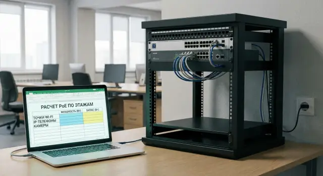
Why bother calculating a PoE budget\n\nA switch’s PoE budget is the total power (in watts) it can deliver to all PoE ports at once. In practice it can run out without obvious signs: ports and cables are connected, but some devices stop receiving enough power.\n\nTypically it goes like this: the network worked fine — APs, phones and cameras powered from the switch with no separate PSUs. Then someone adds two more APs in meeting rooms, and suddenly an old camera starts rebooting and a phone on another floor just goes dark. The reason is usually not a defect but that total consumption exceeded the switch’s limit and the switch started disabling or capping power on some ports.\n\nMost commonly PoE powers Wi‑Fi APs, IP phones, IP cameras (especially with IR and PTZ), as well as intercoms and access controllers.\n\nRemember there are two limits at once:\n\n- the switch’s total budget in watts\n- the per‑port limit (how many watts one jack can provide), which depends on 802.3af/at/bt and the model\n\nThe calculation task is simple: estimate each device’s consumption, sum them per switch and floor, include a margin for peaks and losses, and after installation verify the numbers against real measurements.\n\n## PoE basics: where the watts come from\n\nPoE always has two sides. PSE (Power Sourcing Equipment) — the source, usually a PoE switch (sometimes an injector). PD (Powered Device) — the consumer: AP, IP phone, camera, access controller.\n\nThe switch feeds power to a specific port but is limited by two boundaries: the per‑port maximum and the switch’s total PoE budget. So you can be within per‑port limits and still not be able to power all devices at once.\n\nTypical power guidance by standard:\n\n- 802.3af (PoE): up to 15.4 W per port (usually up to ~12.95 W available to the device)\n- 802.3at (PoE+): up to 30 W per port (usually up to ~25.5 W to the device)\n- 802.3bt (4‑pair PoE): Type 3 up to 60 W (about 51 W usable), Type 4 up to 90 W (roughly 71–73 W)\n\nThe difference between “per port” and “to the device” comes from cable losses and internal electronics. When calculating, look not only at the label “30W PoE+” but at how many watts actually reach the PD.\n\nPoE “Class” (0–8) helps the switch estimate a device’s appetite but does not guarantee real consumption. An AP may normally draw 10–14 W but on peak (many clients, high transmit power, multiple radios, USB active) climb toward the PoE+ limit.\n\nIf the total budget is insufficient, the switch will choose who to power. A new port may not come up, some ports will be disabled, APs will reboot, or cameras may lose IR or start cycling reboots.\n\n## How to collect input data for APs, phones and cameras\n\nAccurate calculation starts with a list of devices and their consumption. A common mistake is to rely only on the standard (e.g. “PoE+”) and either assume the maximum for safety or take typical consumption values.\n\nFirst collect the datasheet numbers. Get them from the datasheet, the controller interface (for Wi‑Fi), device specs, or the rating on a PSU. If unsure about operating modes, use the device’s declared maximum consumption.\n\nIt’s useful to split consumption into modes:\n\n- normal operation\n- peak (when features are active)\n- cold start (short spikes during boot, heater warm‑up, IR turn‑on)\n\nTo later summarize everything in a table, record for each model:\n\n- model and quantity (by floor or zone)\n- power standard (802.3af/at/bt) and PoE class if listed\n- power: typical and maximum (W)\n- what causes peaks (IR, heater, USB, motor)\n- where the port is located (switch, rack, floor)\n\nType‑specific notes:\n\nWi‑Fi AP consumption varies with radio count (2×2, 4×4, tri‑band), bands (2.4/5/6 GHz), channel width and extra functions (USB, BLE/IoT, boosted transmit power). An AP may normally draw 11–13 W but under load with extra modules rise toward the PoE+ cap.\n\nCameras usually surprise with IR, spotlights, PTZ motors and heaters. A camera may use 6–8 W by day but significantly more at night with IR and heating enabled.\n\nIP phones peak with screen/backlight, speakerphone, Wi‑Fi module and connected expansion panels. Count expansion consoles as an additional power draw, not a minor detail.\n\nOnce all data are in a consistent format, you only need to sum them per switch and check the limits.\n\n## Calculation formulas: quick and simple\n\nTo avoid running out of power after adding “a couple more APs,” keep two checks in mind: the switch’s total watt limit and each port’s standard limit.\n\n### Four formulas that cover most tasks\n\n- Group budget: W_group = N × P, where N is the number of devices and P is the power per device (W).\n- Sum per switch: W_PD = Σ(W_group).\n- Budget condition: W_switch ≥ W_PD + W_margin.\n- Margin: W_margin = W_PD × k, where k is typically 0.2–0.3 (i.e. plan 1.2–1.3× the sum).\n\nAlso check the port: P_port_max ≥ P_device. If a switch has PoE+ (802.3at) ports up to 30 W, but the device needs 35–45 W, it either won’t boot or will be power‑capped. This is typical for “heavy” APs, PTZ cameras and outdoor heaters (PoE++).\n\nMini checks before final numbers:\n\n- Use the device’s rated maximum if you’re unsure about modes.\n- Treat heavy devices separately and assign them to specific ports.\n- Don’t mix devices on different switches in one total if they’re not on the same switch.\n\nExample: a 24‑port PoE+ switch has 8 cameras at 12 W and 6 APs at 18 W.\n\nW_PD = 8×12 + 6×18 = 96 + 108 = 204 W.\n\nWith 25% margin: 204 × 1.25 = 255 W. A switch with 250 W PoE budget would be marginal; 370 W gives room for expansion.\n\n## Power reserve: avoiding mistakes from losses and peaks\n\nDesigning to the exact sum almost always ends badly: add a couple cameras, move an AP, turn on an outdoor heater and the budget is exceeded.\n\nCable losses rarely appear as a separate line in specs, but long runs increase risk. Near 80–90 m you have less room for error: cable quality, terminations, patch panels and temperature in enclosures matter.\n\nMany devices have consumption peaks. A camera may switch on IR at night and draw more. An AP grows in power under heavy client load and with multiple radios. In hot rooms equipment runs hotter and you need extra margin.\n\nPractical rule: don’t plan total PoE load above 70–80% of the switch’s rated budget. The rest is buffer.\n\nA handy scheme:\n\n- Operational sum = sum of “typical” watts per port\n- Planned budget = operational sum × 1.25 (minimum +25%)\n\nAdditionally, plan for growth: leave 10–20% of PoE ports free, not just watts. A port with no available PoE is as useless as no port at all.\n\nIf you have critical zones (cash desks, security posts, server room), give them an untouchable reserve. It’s easier to do this during equipment selection and power design.\n\n## Example table for switches and floors (template)\n\nWhen calculating PoE budgets, it’s easiest to keep a single table showing where each switch is, which devices are on which ports, how many watts they may request at peak, and how much reserve remains.\n\n| Building | Floor | Rack | Switch | Devices | Qty | W per 1 (nom.) | W per 1 (peak) | PoE (af/at/bt) | Reserve per port, W | Total nom., W | Total peak, W | Comment |\n|---|---:|---|---|---|---:|---:|---:|---|---:|---:|---:|---|\n| A | 2 | R‑2 | SW‑2‑01 | Wi‑Fi AP | 8 | 13 | 25 | at | 30 | 104 | 200 | Peak during warm‑up/full load |\n| A | 2 | R‑2 | SW‑2‑01 | IP phone | 20 | 4 | 7 | af | 8 | 80 | 140 | Includes margin for backlight/modules |\n| A | 2 | R‑2 | SW‑2‑01 | IP camera with IR | 12 | 8 | 15 | at | 18 | 96 | 180 | Night with IR/heater |\n| | | | | TOTAL for SW‑2‑01 | 40 | | | | | 280 | 520 | Compare with switch PoE budget |\n| | | | | TOTAL for floor 2 | 40 | | | | | 280 | 520 | How many PoE ports needed on the floor |\n\nTo show risk at a glance add three computed fields: switch PoE budget (e.g. 370 W), % load at peak (=Total peak / budget) and final with margin (=Total peak × 1.2 or × 1.3).\n\nRule of thumb: if peak is 70–80% of the budget you can still add a few APs. If it’s 90%+, a new device may drop power on some ports, especially at night (IR) or during mass reboots.\n\n## Step‑by‑step PoE budget calculation before procurement\n\nIt’s better to calculate carefully once than to figure out why new devices won’t come up or reboot at night.\n\nKeep the calculation in a single file and tie it to real points: floor, telecom rack, switch, port.\n\n1) List all PDs by floor and rack: APs, IP phones, cameras, intercoms, controllers. Mark what will be added in the next 3–6 months.\n\n2) For each device set power: nominal and peak. Use datasheet values or, if unknown, a typical peak. Also note the required standard (802.3af/at/bt).\n\n3) Assign devices to specific switches and ports. Check the port limit:\n\nP_device_peak <= P_port_max\n\n4) Sum per switch and add a margin:\n\nPoE_budget_switch = sum(P_peak_all_ports) × (1 + margin)\n\nCommon margin is 20–30%, and for cameras with IR/heaters or PTZ use the higher end.\n\n5) Compare the result with the switch datasheet: total PoE budget and max per port. If total is OK but port limit fails, you’ll need PoE+ or PoE++ on those ports or a separate injector for specific devices.\n\nMini example: on floor 2 plan 6 APs at 18 W peak and 8 phones at 7 W peak.\n\nPeak sum = 6×18 + 8×7 = 164 W. With 25% margin ≈ 205 W. A switch with 190 W budget is risky; 240 W is comfortable.\n\n## Common mistakes that make PoE run out\n\nSame scenario repeats: everything worked, they add "a couple more APs" and some cameras or phones lose power. Usually the cause is planning errors.\n\n- Relying only on af/at/bt and not checking wattage for the specific model and its peaks.\n- Ignoring cameras’ night modes: IR and heaters significantly increase consumption.\n- Dumping heavy loads onto one switch (PTZ + powerful APs), which often causes the “light” devices to suffer first.\n- Forgetting per‑port limits. The total budget may be large but if max per port is 30 W, a 45–60 W device won’t boot.\n- Assuming zero margin and thinking “we’ll add another switch later.” Usually it ends with a field call and downtime.\n- Not checking the switch’s power supply: sometimes the high PoE budget is only available with an upgraded or second PSU.\n\nQuick checklist before expansion:\n\n- Verify rated (typical and max) consumption for every AP, camera and phone.\n- Check the switch’s max per port and its total PoE budget, not just “PoE+ on 24 ports.”\n- Assess camera night mode (IR/heater) and AP peaks separately.\n- Distribute heavy devices across multiple switches or use dedicated PSUs.\n- Leave power margin so adding 1–2 devices won’t break the network.\n\n## Short checklist before installation and after expansion\n\nUse this checklist to quickly ensure power won’t hit limits. Keep it in project notes before installation and repeat it after changes with actual data.\n\n- Record “how many ports are needed now” and “how many in one year.” Often the shortage is PoE ports rather than watts.\n- Compare total power with switch budget including margin. If it’s tight, that’s already a risk.\n- Mark ports where a device needs more than 15.4 W or more than 30 W. For those prepare PoE+ or PoE++.\n- Spread heavy devices across different switches or power units (if separate).\n- Add extra reserve for long runs, outdoor and cold places (heaters, IR, higher transmit power).\n\nPractical tip: after installation log actual PoE load on a typical day and during peak (evening for cameras, business hours for Wi‑Fi). When expanding, compare new values with these measurements.\n\n## Realistic example: three‑floor office and “a couple more APs”\n\nImagine a three‑floor office. Each floor has one telecom rack and its own 24‑port PoE switch. Devices vary: floor 1 has more cameras, floor 2 more phones, floor 3 more Wi‑Fi.\n\nUse these rated values: IP camera — 10 W, PTZ camera — 25 W, IP phone — 7 W, AP — 16 W (peak 22 W). Margin K = 1.25.\n\nFormula per floor (switch):\n\nP_total = (Σ (qty_device × P_device)) × K\n\n| Floor | Devices (qty) | Sum, W | With margin (×1.25), W | Switch PoE budget, W | Result |\n|---|---|---:|---:|---:|---|\n| 1 | 10 cameras ×10 + 2 PTZ ×25 + 2 AP ×16 | 182 | 228 | 195 | Not enough (-33) |\n| 2 | 20 phones ×7 + 2 cameras ×10 + 2 AP ×16 | 192 | 240 | 370 | OK |\n| 3 | 8 AP ×16 + 4 phones ×7 + 2 cameras ×10 | 176 | 220 | 195 | On the edge (+25 without margin won’t save) |\n\nCheck two constraints:\n\n- Total budget: floor 1 lacks total power even if ports are enough.\n- Port power: PTZ (25 W) and APs with peaks (up to 22 W) need PoE+ (802.3at). If some ports are only 802.3af, these devices may not boot or will be unstable.\n\nTypical fixes: move some regular cameras to another rack (if possible by cabling), choose a switch with a larger PoE budget or add a small separate PoE switch for cameras. For floor 3 plan for growth: “a couple more APs” will add ~32 W (up to 44 W peak) and the margin will disappear quickly.\n\n## Next steps: lock the calculation and plan for growth\n\nOnce the calculation matches reality, don’t lose it. Otherwise in six months a new camera or “a couple more APs” appears and you’re back troubleshooting.\n\nMake a PoE "passport" for the network: port, device, PoE standard and reserved watts. A practical rule: any new device goes into the passport first, then to the rack.\n\nMove from a one‑time calculation to ongoing control:\n\n- Record the PoE passport: floor, rack, switch, port, device, planned watts and margin.\n- Monthly (and after changes) record actual per‑port PoE consumption and compare with calculations.\n- Note where new APs, phones or cameras are likely within 6–12 months.\n- Decide in advance what to do when load grows: add a switch, replace it with a higher‑budget model, or move devices to another rack.\n- Keep a standard margin (e.g. 25%) so the team makes consistent choices.\n\nIf you need help designing power and choosing equipment for real loads, it’s usually easier to work with a system integrator. For example, GSE.kz (gse.kz) does system integration and infrastructure solutions — on the project stage they can pre‑check PoE budgets, port limits and growth margins.
FAQ
What is a switch PoE budget in simple terms?
It’s the total amount of power (in watts) the switch can provide to all PoE ports at the same time.\n\nEven if there are many ports and each one "supports PoE", the total budget can run out — then some devices won’t start or will begin rebooting.
Why does PoE “suddenly run out” although everything used to work?
Because the issue often appears gradually: you add 1–2 devices and the **older** ones start to "float".\n\nTypical symptoms:\n\n- a camera goes into cyclic reboots\n- a phone loses power\n- an AP boots but drops under load\n- a camera’s IR/back‑heater turns off at night
Where in the switch specs do I find the numbers needed for the calculation?
Look for two specs in the switch datasheet: \n\n- **PoE budget (W)** — the total budget for the switch\n- **Max per port (W)** — the maximum for one port\n\nBoth matter: you may have a large total budget but weak ports, or powerful ports but a small total limit.
What’s the difference between port limit and total PoE budget?
Port limit is “how much can go to one jack”, total budget is “how much can go to all ports combined”.\n\nExample: every device fits into 15–25 W per port, but there are many of them and together they exceed the budget — some ports will be disabled or power‑capped.
What PoE standards exist and how many watts do they provide?
Use the standard as a guide but check real available power: \n\n- **802.3af**: up to 15.4 W per port (the device usually gets less)\n- **802.3at (PoE+)**: up to 30 W per port\n- **802.3bt**: Type 3 up to 60 W, Type 4 up to 90 W\n\nIf a device can draw more than the port limit at peak, it may not boot or will be power‑limited.
What power reserve should I include in the PoE calculation?
Basic approach — use the device’s rated maximum and sum by switch.\n\nThen add a margin:\n\n- typically **+20–30%** to the sum\n- aim to keep switch PoE load **below 70–80%** of its rated budget\n\nThis way «a couple more APs» won’t be a surprise.
What causes consumption peaks for cameras, Wi‑Fi APs and phones?
Main peak sources: \n\n- **IR illumination, spotlights, heaters** on cameras (especially at night)\n- **PTZ motors** (pan/tilt/zoom)\n- for Wi‑Fi: multiple radio modules, high traffic, extra modules (e.g. USB)\n- for phones: backlight, screen, speakerphone, expansion modules\n\nIf unsure — calculate by the device’s maximum mode.
Should I account for cable losses and cable length?
Don’t assume all 30 W marked on a switch reaches the device. Some power is lost:\n\n- on long runs (especially near 80–90 m)\n- because of cable quality and terminations\n- at patch panels/connections\n\nIn practice: give more margin on long lines and avoid designing right up to the limit.
How to quickly gather input data for PoE budget calculation?
Collect a small table per model: \n\n- how many devices and where they’re installed (floor/closet/switch)\n- power standard (af/at/bt) and PoE class if present\n- typical and maximum power\n- what causes peaks (IR, heater, USB, motor)\n\nIf data is missing — use the device’s maximum rating or the onboard PSU rating.
What to do if PoE devices reboot or don’t power on?
Start with a short checklist: \n\n- compare the total per switch and per port limits for the heavy devices\n- check actual PoE load on the switch (total and per port)\n- temporarily disconnect/relocate the most power‑hungry devices to confirm the cause\n\nTypical fixes: increase PoE budget (different switch/PSU), distribute devices across switches, or use a PoE injector for a few heavy ports.